

Selection of electrolytic capacitors is mainly based on their reliability. Beside this property, the evaluation of environmental performances of such devices is crucial due to their wide dissemination and utilization of critical raw materials for their production. Starting from the environmental analysis of the stages of selection and supply of raw materials, it is possible to improve the sustainability of the manufacturing process of a capacitor. In addition, the use stage and end-of-life of the devices can be analyzed to evaluate their entire life cycle. In this study, LCA (Life Cycle Assessment) methodology is applied to perform a comparative analysis between two types of aluminum electrolytic capacitors. These products can be applied in different sectors as industrial, inverter and UPS, solar, medical and tractions systems. The aim of this study is to compare the environmental impact due to the stages of production (from the raw materials supply to the assembly) and end-of-life (recycle or disposal of wastes) of two aluminum electrolytic capacitors, which are characterized by different internal designs but are manufactured by the same producer.
The paper was presented by Chiara Moletti, Department of Chemistry, Materials and Chemical Engineering “Giulio Natta”, Politecnico di Milano, Italy at the 3rd PCNS 7-10th September 2021, Milano, Italy as paper No.1.8.
ALUMINUM CAPACITORS & LIFE CYCLE ASSESSMENT INTRODUCTION
INTRODUCTION
Modern life lays its foundations on the smart use of functional materials that are increasingly present in everyday life products and devices. The growth of the last decades is based on the wide application of semiconductor and passive components. Capacitors are one of the most common passive components and several types of capacitors are nowadays produced worldwide, like array capacitors (ACs), aluminum electrolytic capacitors (AECs), aluminum organic polymer capacitors (AOPCs), ceramic capacitors (CCs), multilayer ceramic capacitors (MLCCs), tantalum electrolytic capacitors (TECs), and supercapacitors [1].
Climate change is one of the main issues of our times. In the last decade, Europe and most of the countries worldwide introduced in their development programs the energy efficiency and independence, limiting the use of fossil fuel and rare earth [2], [3]. The growth of producers and users’ awareness about the environmental issue, together with the spread of policies aimed at the reduction of the human activities impacts on the environment, led to the necessity to manage the resources exploitation during design and manufacturing of products, and to use devices as much efficient as possible. This goal can be reached converting traditional systems into energy efficient systems and capacitors play an important role in this game [4]–[6]. One of the main fields of application of capacitors is the automotive sector, that requires an extensive use of these devices due to the rise of alternative propulsion technologies, where a proper electric management is crucial [7], [8]. For example, AECs are typically employed for small systems like for example air conditioning, automatic windows and engine controls [9].
Capacitors can help the efficient use of energy, nevertheless they trend to reduce the power factor of systems using harmonics that may decrease the overall efficiency.
Aluminum electrolytic capacitors have many applications in a wide range of sectors (e.g. industrial, medical, UPS). This type of capacitors is the most common thanks to their low price, high volumetric efficiency, and the possibility to select a proper voltage range and capacity depending on their application [10]. They are used when attenuation of voltage ripple, electric energy storage, and a large capacitance are required. Typical values of capacitance range from 0.1 μF to 2.7 F in these devices, and leakage current is not a crucial factor [11]. Their generally short lifetime respect to the other components of a device usually determines the service life of the system, for aluminum electrolytic capacitors this span of life ranges from 5000 to 25000 hours [12].
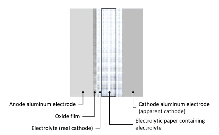
The selection of materials is crucial to produce capacitors, the AECs have the same internal structure but the specific materials which constitute them can vary. The positive pole is formed by an anodized aluminum foil that constitutes the anodic surface, which is in contact with a liquid electrolyte, that acts as cathode, in which a set of paper spacer is soaked. The electrolyte main components are a solvent and a solute, typically ethylene glycol and ammonium borate. This group of components is contained in an aluminum can and sealed in a polymeric case [13]. The assembly is composed to limit as much as possible the evaporation of the electrolyte that is one of the main causes of the decrease of the capacitance and the device wear-out.

The Life Cycle Assessment (LCA) is a standardized methodology through which it is possible to quantify and evaluate the environmental performances of a product or of a process [14], [15]. This study consists in an LCA of the manufacturing stage of two types of aluminum electrolytic capacitors having different internal design and manufactured by the same producer. The stage of production of the component is crucial since the selection of materials and assembly strategies influences the environmental performances of the capacitor. LCA is an important tool to evaluate the environmental impacts of capacitors, especially during the design phase of the devices. The growing production of these components is reflected in a tangled network of suppliers and manufacturers [16], [17].
RESEARCH & LIFE CYCLE ASSESSMENT
RESEARCH METHOD
The goal of this study is to assess the environmental performances of two types of aluminum electrolytic capacitors, namely “Type 1” and “Type 2”. The two capacitors differ for the electrolyte source and composition: Type 2 electrolyte is an evolution of Type 1 electrolyte, which is studied and sourced from with a specialty chemicals producer partner. . The study of the environmental impacts may lead to the adoption of virtuous policies that, preserving the device performances, decrease the production footprint on the environment.
Functional unit
Since both capacitors are produced in different sizes, a reference product has been selected for the analysis of the environmental impact to define the functional unit (FU) of the LCA study. Hence, the FU is the capacitor having a mass of 0.06 kg.
System boundaries
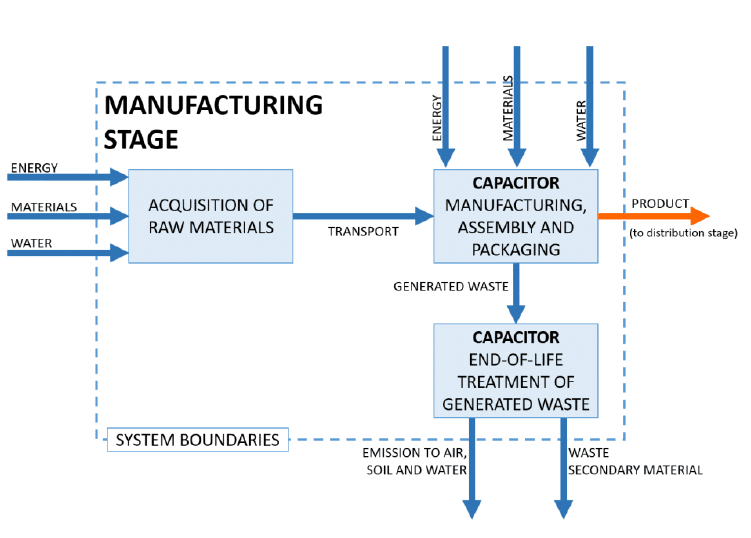
The LCA study has been carried out on the basis of the standard EN 50693:2019 [18] which establishes specific requirements for the environmental analysis of electrical products. The study focuses on the manufacturing stage to assess and compare the environmental impact related to the production of the two types of aluminum electrolytic capacitors. According to the standard, the manufacturing stage has been subdivided in the following steps: acquisition of raw materials, transport to manufacturing site, component manufacturing, end-of-life treatment of generated waste. The boundaries of the system are schematized in Figure 2.

LIFE CYCLE INVENTORY
The acquisition of the raw materials includes all the processes related to the extraction and production of such materials. In this case the main raw materials are aluminum, the electrolyte, paper, and the dielectric envelope of the device.
The second process unit is the transport of raw materials to the manufacturing site (e.g. ship or land transport), in this phase the amount of transported material is calculated together with all the data about distances and packaging related to the supply to the production site. The packaging used during transport have been excluded from the model of the system since their impact is negligible with respect to the other contributions, or it is reused as in the case of wooden pallets, and hence it is part of the cut-off of the system according to the EN 50693:2019 [18].
The input flows in the capacitor manufacturing, assembly and packaging process unit are raw materials, energy (gas and electricity) and water related to the manufacturing operations. The outputs are the product, the scraps of aluminum, paper and plastic materials.
The last step is the evaluation of the end-of-life which includes the management, treatment and disposal of scraps and waste generated during manufacturing; in addition, it includes the transport to the center of waste collection. This stage is crucial because the possibility of recycling or reusing waste materials can be evaluated and accounted into the lifecycle of the product. For example, only a portion of the discarded paper and part of the aluminum scraps can be recycled whilst all materials contaminated by the electrolyte or plastic materials are sent to incineration. Moreover, the washing water are collected and sent to sewage treatment.
The life cycle inventory (LCI) has been realized using primary data for the transport, production and end-of-life stages while raw materials production step has been modelled using Ecoinvent 3.6 database [19].
Life cycle impact assessment
The quantification of impacts is performed with the software SimaPro®, version 9.1.1.1, and the indicators have been computed according to the indications given by ISO 50639 [18] and ISO 15084 [20] standards. Among the results, the focus has been set on the Global Warming Potential (GWP) which quantifies the impact category of climate change, that, for the purposes of our research, is the most revealing result.
RESULTS & CONCLUSIONS
RESULTS
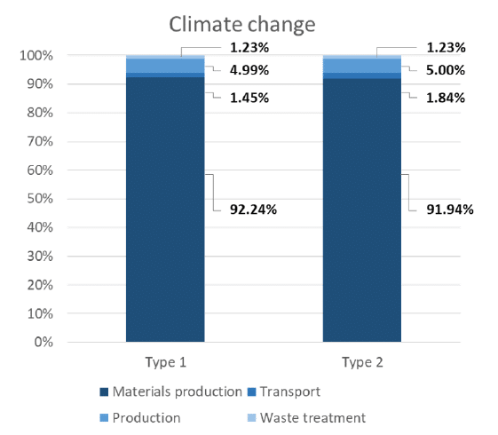
The contributions of each process unit of the manufacturing stage to the GWP indicator for Type 1 and Type 2 AECs are reported in Figure 3. The difference between the environmental performances in terms of climate change of the two capacitors is very small (i.e. 0.01% in favor of Type 2), the main differences are detected between two of the process units: raw materials production (+0.30% for Type 1 vs Type 2) and transport (-0.39% Type 1 vs Type 2).

The detailed contributions to climate change of the production of each raw material (i.e. aluminum, electrolyte, paper and case) and their transport are shown in Figure 4. In both cases the main difference can be mainly attributed to the electrolyte, in Type 1 it has higher impact in terms of raw materials production (+0.32% vs Type 2) while in Type 2 the electrolyte has greater influence on the transport (+19.23% vs Type 1). It is worth nothing that the long-range transport in Electrolyte 2 is counteracted by a more complex transformation of raw material required to produce Electrolyte 1. It means that Type 2 can be a viable alternative to Type 1 capacitor.
Considering a reference expected life of the two capacitors, their energy consumptions have been calculated according to the Equation 1, the consequent environmental impacts have been assessed considering a global energy mix value.

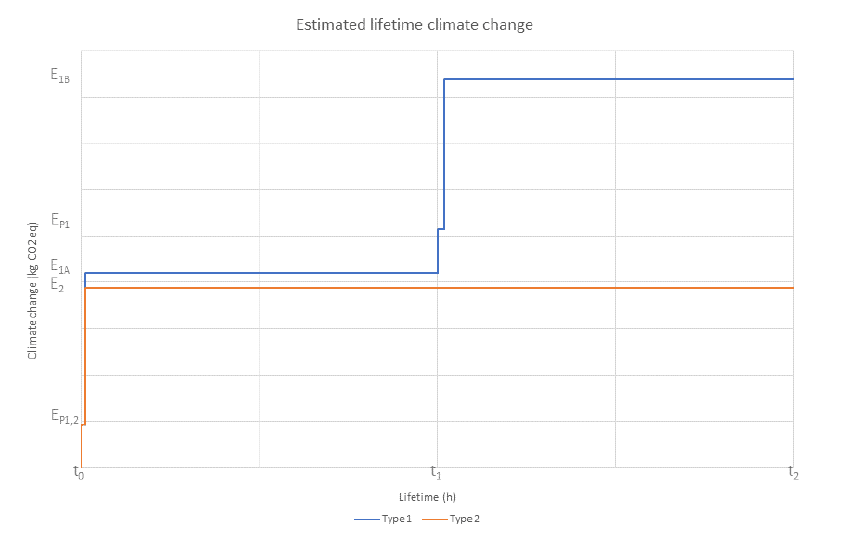
The trends of the GWP indicator resulting for the estimated lifetime of the two products are plotted in Figure 5. EP1,2 is the emission due to the production of the one capacitor of Type 1 and one of Type B at the beginning (t0) of the estimated service life (t2); E2 is the climate change due to the operation of Type 2 device, it corresponds to the emissions of the product during the lifetime t2. Differently, two Type 1 capacitors (1A and 1B) are necessary to achieve the same expected lifetime t2, the first one reaches the emission value E1A during its lifetime t1, that is half of the target time t2, and with the introduction of a second Type 1 device, 1B, the overall contribution to climate change is E1B, over a lifetime t2. Within the total emissions, the GWP contribution due to the production of the 1B assembly, EP1, has to be added once again. Hence, the solution employing one Type 2 capacitor gives less than half of the polluting emissions with respect to the use of two Type 1 products during a reference expected lifetime.

CONCLUSIONS
The study analyzed two different AECs, which differ for the electrolyte Type 1 or Type 2. The LCA study of the two capacitors has highlighted very restricted differences in terms of environmental performances, despite their different internal design. An outline of a typical estimated lifetime has been proposed, considering the different durability of the two types.
The result is that, considering the energetic consumption during the reference estimated lifetime, the Type 2 device is characterized by a much lower energy consumption as well as significantly lower emissions, less than half of the Type 1.
Consequently, the accurate selection of the material is crucial to improve the performances of the device, provided that the production and supply of raw materials are not environmentally detrimental with respect to the alternatives.
In the present study, it is demonstrated that the change of electrolyte gives better environmental performances of Type 2 device with respect to Type 1; moreover, due to the higher operational performances during the service life of the product, it results to be the best solution among the 2 analyzed.
REFERENCES
[1] L. Smith, T. Ibn-Mohammed, S. C. L. Koh, and I. M. Reaney, “Life cycle assessment and environmental profile evaluations of high volumetric efficiency capacitors,” Appl. Energy, vol. 220, no. March, pp. 496–513, 2018, doi: 10.1016/j.apenergy.2018.03.067.
[2] X. Chen, Q. Fu, and C. P. Chang, “What are the shocks of climate change on clean energy investment: A diversified exploration,” Energy Econ., vol. 95, p. 105136, Mar. 2021, doi: 10.1016/j.eneco.2021.105136.
[3] M. Sun, X. Xu, L. Wang, C. Li, and L. Zhang, “Stable energy, energy inequality, and climate change vulnerability in Pan-Third Pole regions: Empirical analysis in cross-national rural areas,” Renew. Sustain. Energy Rev., vol. 147, p. 111197, Sep. 2021, doi: 10.1016/j.rser.2021.111197.
[4] P. Thollander, M. Danestig, and P. Rohdin, “Energy policies for increased industrial energy efficiency: Evaluation of a local energy programme for manufacturing SMEs,” Energy Policy, vol. 35, no. 11, pp. 5774–5783, Nov. 2007, doi: 10.1016/j.enpol.2007.06.013.
[5] J. R. Miller and A. F. Burke, “Electrochemical capacitors: Challenges and opportunities for real-world applications,” Electrochem. Soc. Interface, vol. 17, no. 1, pp. 53–57, Mar. 2008, doi: 10.1149/2.f08081if.
[6] P. J. Hall et al., “Energy storage in electrochemical capacitors: Designing functional materials to improve performance,” Energy Environ. Sci., vol. 3, no. 9, pp. 1238–1251, 2010, doi: 10.1039/c0ee00004c.
[7] J. Van Mierlo, P. Van den Bossche, and G. Maggetto, “Models of energy sources for EV and HEV: Fuel cells, batteries, ultracapacitors, flywheels and engine-generators,” J. Power Sources, vol. 128, no. 1, pp. 76–89, 2004, doi: 10.1016/j.jpowsour.2003.09.048.
[8] W. Lhomme, P. Delarue, P. Barrade, and A. Bouscayrol, “Maximum Control Structure of a Series Hybrid Electric Vehicle using Supercapacitor,” EVS’21 : The 21st Worldwide Battery, Hybrid and Fuel Cell Electric Vehicle Symposion & Exhibition. 2005, Accessed: Jun. 09, 2021. [Online]. Available: https://infoscience.epfl.ch/record/88081.
[9] A. Nishino, “Capacitors: Operating principles, current market and technical trends,” Journal of Power Sources, vol. 60, no. 2. Elsevier, pp. 137–147, Jun. 01, 1996, doi: 10.1016/S0378-7753(96)80003-6.
[10] K. Laadjal, M. Sahraoui, A. J. M. Cardoso, and A. M. R. Amaral, “Online Estimation of Aluminum Electrolytic-Capacitor Parameters Using a Modified Prony’s Method,” IEEE Trans. Ind. Appl., vol. 54, no. 5, pp. 4764–4774, 2018, doi: 10.1109/TIA.2018.2836923.
[11] G. Sainadh Gudavalli and T. P Dhakal, “Simple Parallel-Plate Capacitors to High–Energy Density Future Supercapacitors,” Emerg. Mater. Energy Convers. Storage, pp. 247–301, 2018.
[12] M. Catelani, L. Ciani, R. Singuaroli, and A. Mannucci, “Electrolytic capacitor lifetime prediction in ground mobile applications,” 13th IMEKO TC10 Work. Tech. Diagnostics 2014 Adv. Meas. Tools Tech. Diagnostics Syst. Reliab. Saf., pp. 164–168, 2014.
[13] V. A. Sankaran, F. L. Rees, and C. S. Avant, “Electrolytic capacitor life testing and prediction,” Conf. Rec. – IAS Annu. Meet. (IEEE Ind. Appl. Soc., vol. 2, pp. 1058–1065, 1997, doi: 10.1109/ias.1997.628992.
[14] ISO, “ISO 14040-2006+A1-2020 Environmental management — Life cycle assessment — Principles and framework.” 2020.
[15] ISO, “ISO 14044-2006-Amd.2-2020 Environmental management — Life cycle assessment — Requirements and guidelines.” 2020.
[16] A. Acquaye, T. Ibn-Mohammed, A. Genovese, G. A. Afrifa, F. A. Yamoah, and E. Oppon, “A quantitative model for environmentally sustainable supply chain performance measurement,” Eur. J. Oper. Res., vol. 269, no. 1, pp. 188–205, Aug. 2018, doi: 10.1016/j.ejor.2017.10.057.
[17] A. Acquaye et al., “Measuring the environmental sustainability performance of global supply chains: A multi-regional input-output analysis for carbon, sulphur oxide and water footprints,” J. Environ. Manage., vol. 187, pp. 571–585, Feb. 2017, doi: 10.1016/j.jenvman.2016.10.059.
[18] ISO, “ISO 50693:2019 Product category rules for life cycle assessments of electronic and electrical products and systems,” 2019.
[19] B. Wernet, G., Bauer, C., Steubing, B., Reinhard, J., Moreno-Ruiz, E., and Weidema, “The ecoinvent database version 3 (part I): overview and methodology. The International Journal of Life Cycle Assessment.” online 21(9), pp. 1218–1230, 2016, [Online]. Available: http://link.springer.com/10.1007/s11367-016-1087-8.
[20] ISO, “EN 15804:2012+A2:2019 Sustainability of construction works – Environmental product declarations – Core rules for the product category of construction products,” no. February 2014, 2020.

