

High voltage Aluminium electrolytic capacitors with working voltages UR > 400 V are the backbone of industrial and automotive electronics. The main application is in the DC-link circuit. The advantage of those capacitors are lower cost compared to other capacitor types, a high CV product and a better cool-ability.
The paper was presented by Thomas Ebel, Centre for Industrial Electronics, Department of Mechanical and Electrical Engineering, University of Southern Denmark, Sønderborg, Denmark at the 3rd PCNS 7-10th September 2021, Milano, Italy as paper No.5.4. and voted by attendees as:
OUTSTANDING PAPER AWARD
Polymer Aluminum Electrolytic capacitors have ca. 10 times lower ESR values as classical Aluminium electrolytic capacitors with liquid electrolyte and are much more temperature stable. So far, they are only available for rated voltages lower than 250 V. It would be therefore favorable to have Polymer Aluminium Electrolytic Capacitors also operating at further higher voltages.
To step forward a new developed breakdown model of classical Aluminium Electrolytic Capacitors will be discussed and first preliminary data of high voltage Polymer Aluminium Electrolytic Capacitors data with rated voltage over 400 V will be presented.
INTRODUCTION
Aluminium electrolytic capacitors are widely used in automotive applications. For low power application with voltages up to 48 V, that are mainly found in auxiliary drives but also mild hybrid EV, typically classical axial or SMD solid polymer electrolytic capacitors are applied [1,2,3]. The working voltage of those commercially available polymer capacitors, based on PEDOT-PSS, varies usually between 14 and 250 V [4]. Recently also higher voltages up to 400 V were reported [5]. For medium and high-power applications, the dc-link capacitors are typically made of metalized film and Aluminium electrolytic capacitors [6,7,8]. The later usually have a typical working voltage of 350 to 450 V, however the metallized film capacitors provide long lifetime under high ripple current load, but metallized film capacitors are big, expensive and limited in temperature exposure over 105°C [9]. For higher dc-link voltages Aluminium electrolytic capacitors need to be connected in series leading to the well-known issue of voltage balancing.
During the last decade wide band gap power semiconductors have become more mature and are now an interesting alternative for silicon-based power semiconductors in automotive applications, since they have the potential to significantly increase the power density of the converters [10,11]. This could be achieved by higher switching frequencies typically leading to smaller passive devices and by higher operating temperatures leading to smaller heat sinks [12, 13].
In this paper we compare model capacitors based on Polymer Aluminum Electrolytic technology versus classical Aluminium Electrolytic Capacitors with liquid electrolyte.
To step forward a new developed breakdown model of classical Aluminium Electrolytic Capacitors will be discussed and first preliminary data of high voltage Polymer Aluminium Electrolytic Capacitors data with rated voltage over 400 V will be presented.
BREAKDOWN THEORY
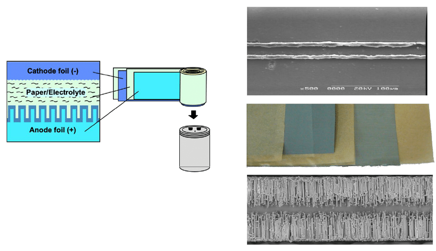
To understand how high voltage polymer capacitors could work the breakdown mechanism at the anodic oxide layers must be understood. Fig.1 shows the principal construction of a high voltage (U > 400 V) Aluminium electrolytic capacitors with liquid or polymer electrolyte. Highly etched anode foils are stacked or wounded with thinner cathode foils, separated by capacitor paper.
Such winding elements for high voltage use are usually impregnated with liquid electrolytes based on mixtures of glycols with inorganic and organic acid salts with ammonia and additives [14].
Recently it was reported that the use of nano dispersed PEDOT-PSS particles could improve the breakdown voltage a lot compared to in situ polymerized versions [5].
The authors have principally investigated the physical fundamentals of breakdown [15] which are summarized here.
The breakdown voltage UB obeys the well-known relation:


(1)
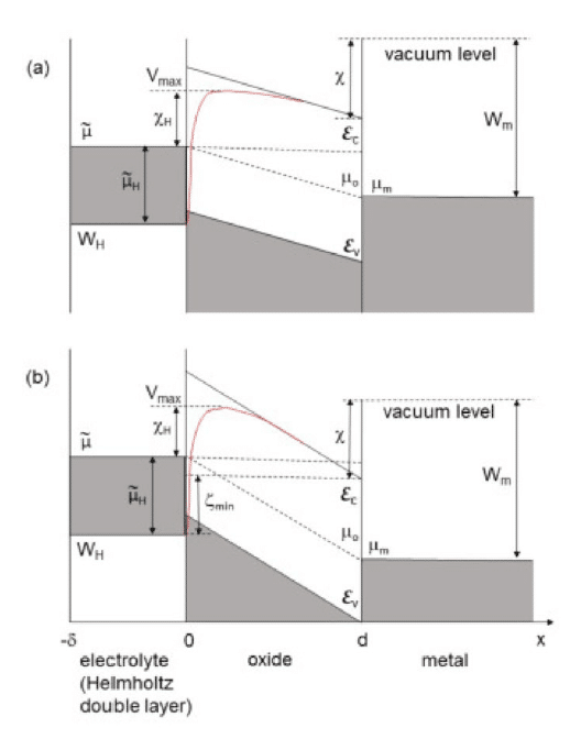
where r is the electrolyte resistivity and the coefficients aB and bB are constant for a given metal and electrolyte composition. This dependence can be derived from first principles basing on the electron band diagram for the metal-oxide-electrolyte system (Fig. 2) [15]. According to the microscopic theory, the coefficients aB and bB are related with the parameters of the Freundlich adsorption isotherm:


(2)
where A is the surface number density of the anions adsorbed at the electrode and C is the volume number density of the same anions in the bulk electrolyte. The latter quantity in turn determines the electrolyte conductivity. Here a is an empirical constant and b is the adsorption exponent which may have any value between 0.1 and 0.7, depending on the concentration and the nature of the solute.
The theory of electrical breakdown in barrier anodic films in contact with an electrolyte allows one to consistently describe this phenomenon. The main points of this new theory are summarized in [15].


Comparisson of Polymer Electrolytic vs LiQUID Electriolytic Model caPacitors
To compare the electrical properties of polymer impregnated and liquid electrolyte impregnated capacitors stack model based capacitors were build (fig. 2) based on the principal construction described in fig. 1.


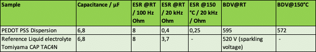
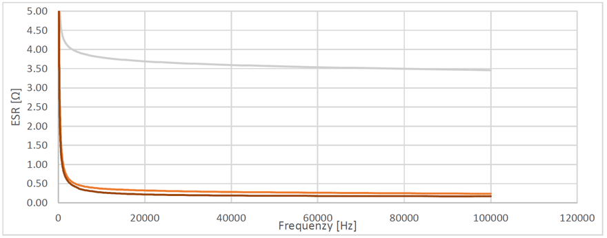
The obtained results of the measurements are summarized in table 1 and Fig. 4.


SUMMARY AND CONCLUSIONS
A new breakdown model was presented. In case of conduction polymer anodic oxide interfaces the situation seems to be very different respect to liquid electrolytes, because smaller ions which could be incorporated into the oxide during the anodization process are missing here and could not serve anymore as sources of the injection current. Therefore, the breakdown model for conduction polymer anodic oxide interfaces must be elaborated more in detail.
The measured data of model capacitors shows that polymer electrolytic capacitors indicate a significant better ESR -temperature and frequency behaviour compared to classical liquid electrolyse. Up to factor of 9 lower ESR values could be obtained. That means, that nine times higher ripple current loads at the same thermal loss could be expected. Such capacitors could also actively be cooled which is a significant advantage vs. metallized film capacitors.
The high frequency behaviour over 20 kHz and the high temperature stability over 125°C makes them best candidates for the application together with the new wide band gap semiconductor like GaN or SiC switching devices.
The temperature dependence of the ESR of the polymer electrolytes is very little compared to liquid electrolytes [1].
The measured breakdown voltage at 150°C for ca. 572 V makes the polymer electrolytes also best suited for high voltage high temperature applications.
However, in particular the leakage current behaviour, vibration resistivity, breakdown behaviour and endurance behaviour must still be investigated in more detail.
REFERENCES
[1] https://en.tdk-electronics.tdk.com/download/173632/7a81baf4ab884c3f4bc3dfb881415101/aluelko-automotive-harsh-environments-pb.pdf
[2] https://industrial.panasonic.com/ww/products/capacitors/polymer-capacitors/hybrid-aluminum
[3] http://www.sunelec.co.jp/common/pdf/eng/e17.pdf
[4] Zhaoqing. “250 V Polymer capacitor series CB”. Beryl Electronic Technology Co., Ltd.
[5] Udo Merker , Klaus Wussow , Katrin Asteman , Wise Chow , Willie Luo , Zhenquan Chen, PCNS 2017.
[6] Winterborne, Dave & Ma, Mingyao & Wu, Haimeng & Pickert, Volker & Widmer, James & Barrass, Peter & Shah, Laxman. (2013). Capacitors for high temperature DC link applications in automotive traction drives: Current technology and limitations. 2013 15th European Conference on Power Electronics and Applications, EPE 2013. 10.1109/EPE.2013.6634382.
[7] Montanari, Davide & Saarinen, Kimmo & Scagliarini, Fabio & Zeidler, Dietmar & Niskala, Matti & Nender, Claes. (2009). Film Capacitors for Automotive and Industrial Applications. 29.
[8] https://en.tdk-electronics.tdk.com/tdk-en/373388/company/press-center/press-releases/press-releases/film-capacitors–dc-link-capacitor-for-new-igbt-modules-/1857564
[9] https://en.tdk-electronics.tdk.com/inf/20/20/db/fc_2009/MKP_B32674_678.pdf
[10] https://www.st.com/content/ccc/resource/technical/document/conference_paper/group0/dc/1d/c6/52/b1/58/43/d7/widebandgap_automotive_evtec_ape_japan.pdf/files/widebandgap_automotive_evtec_ape_japan.pdf/jcr:content/translations/en.widebandgap_automotive_evtec_ape_japan.pdf
[11] https://www.energy.gov/sites/prod/files/2014/03/f13/ape050_tolbert_2013_o.pdf
[12] https://www.electronics-cooling.com/2013/03/measuring-and-predicting-junction-temperature-thermal-factors-influencing-reliability-in-gan-hemts/
[13] Integration Concept for a Traction Inverter with 3D-Printed Embedded Cooling Technology realizing Highest Power Density CIPS 2018 ; Int’l Conference on Integrated Power Electronics Systems Jasper Schnack, Dominik Hilper, Ulf Schümann, Ronald Eisele, University of Applied Sciences Kiel, Kiel, Germany Frank, Osterwald, Holger Beer, Danfoss Silicon Power GmbH, Flensburg, Germany, Thomas Ebel, FTCap Fischer & Tausche Capacitors GmbH, Husum, Germany
[14] T. Ebel, Electrolyte solution for electrolytic capacitor, EU Patent, EP 1425768, 2002.
[15] V. Bordo and T. Ebel, First-principles theory of electrical breakdown in barrier anodic films in contact with an electrolyte, 136490 354 Electrochimica Acta, 2020.

