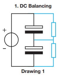
In the design of a capacitor bank, it is important to balance the capacitors for both DC and transient signal. This paper written by Vishay explains the balancing methods that applies to aluminum electrolytic capacitors.
If two capacitors are placed in series to a DC voltage source U, the midpoint-voltage is not automatically 0.5 x U. The voltage distribution is dominated by the leakage current, which varies by capacitor and is voltage-dependent. The capacitor that has the larger leakage current at 0.5 x U will have a somewhat smaller voltage drop than the other capacitor, leading to an equalized leakage current through both capacitors.
Depending on the difference in leakage current, this could lead to voltage drops larger than the rated voltage, which could result in decreased lifetime or even early failure. Balancing the DC voltage is therefore necessary. This can be done in a passive way as shown in Drawing 1: two resistors in parallel to the capacitors, with values typically calculated as Rmax = (2 x Umax. – U)/Ileak– 5min x Umax. would be the maximum allowable voltage drop across one capacitor (typically Urated). U is the applied DC voltage. Ileak-5min is the DC leakage current as measured after five minutes of applied rated voltage.
The disadvantage of this way of passive balancing is a relatively high efficiency loss, typically from 1 % to 5 %. This is unacceptable in applications like solar inverters, where the need for maximum efficiency dominates the market. Here designers work with active balancing.
Practical advice: if one of the capacitors in a series connection fails, replace both capacitors with two fresh ones from the same batch, to ensure that the leakage currents of both devices in one branch are roughly equal.
Two capacitors in series connected to a power source will react differently to transient signals. For the change in voltage drop over a capacitor, C1 holds ∆ V1 = 1/C1 ∫ I1(t)dt. With a fixed current (I=I1 =I2) running through C1 and C2, we get C1 ∆ V1 = C2*∆ V2, or ∆ V1/∆ V2 = C2/C1. So the change in midpoint voltage is determined by the ratio of the capacitances. This leads to simple requirements from designers: C1 = C2. This is correct from a theoretical point of view, but manufacturers of electrolytic capacitors work with a typical production variation of ± 20 % in capacitance in their specifications. This tolerance is set on all produced capacitors; within one batch, variation is less. Typically, the variation within one batch is ± 6 % (total spread from a minimum to maximum capacitance of 12 %).
Practical advice: use capacitors from the same production batch per individual branch. When switching to another production batch, one should measure the 100 Hz capacitance value of all capacitors in that specific branch to exclude unbalanced branches. The same holds for the replacement of capacitors at failure. Remove all capacitors from the branch and replace with fresh ones from the same batch.
