
This paper on Qualification Challenges and Approaches for Cryogenic Temperature Testing of EEE Components in the ESA ARIEL Science Mission presented by Manuel Sánchez Ruiz, Alter Technology, Spain received BEST PAPER AWARD during the 5th Space Passive Component Days (SPCD), an International Symposium held from October 15th to 18th, 2024, at ESA/ESTEC in Noordwijk, the Netherlands. Published under permission from ESA SPCD organizers.
ESA’s ARIEL mission requires EEE components to withstand extreme temperatures, necessitating careful selection and testing. The testing flow involves cryogenic validation, thermal cycling, and functional characterization to ensure component reliability under mission conditions. The testing covers a range of components, including passives and cables, to validate their performance in the cold environment of the ARIEL payload.
A testing flow is described for characterizing the performance of electronic components at cryogenic temperatures, specifically focusing on a microswitch manufactured by PETERCEM. The testing involves thermal cycling and electrical measurements at both room temperature and 40K to assess the switch’s functionality and durability. Initial results show the microswitch successfully switching at 40K with no significant degradation in force-displacement or electrical characteristics.
Testing of European Passive EEE parts at extreme low temperatures aims to create a database for future missions. Initial results from de-risking tests on a PETERCEM microswitch are positive.
Key Points
- Cryogenic Testing Importance: Essential for ensuring the reliability of EEE components in space missions operating at extremely low temperatures.
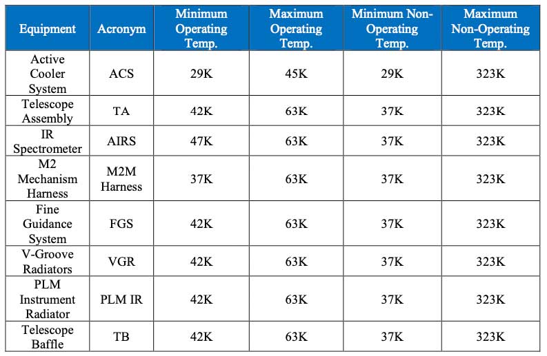
- ESA ARIEL Mission Temperature Range: Operating temperatures range from 29K to 100K, surpassing the classical military range of [-55, +125] ºC.
- ALTER’s Role in ESA ARIEL Mission: ALTER, as the Components Procurement Parts Agency (CPPA), is responsible for component selection and testing for the ESA ARIEL science mission.
- Mission Goal: Characterize and study exoplanets to correlate their characteristics with their host stars.
- Testing Candidate Selection: A comprehensive analysis was performed to select testing candidates based on the temperature values seen by the parts, considering the most stringent conditions affecting similar components.
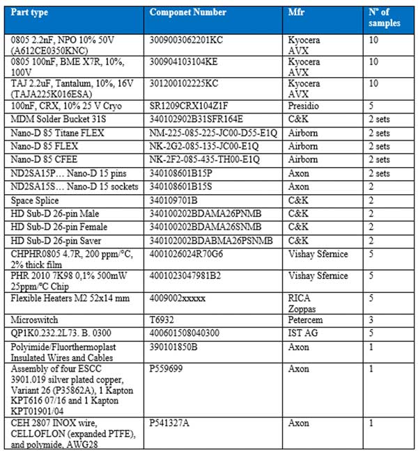
- Testing Coverage: Covers all families of connectors, cables, capacitors, resistors, thermistors, flexible heaters, and a microswitch.
- Technology Corner Coverage: Selects the most critical component from each family/series, such as the largest and highest resistance value resistor.
- Testing Strategy: Groups parts like connectors and cables to reduce the number of test campaigns, lowering costs and lead time.
- Capacitor: 100nF, CRX, 10% 25 V, Kyocera TAJA225K016ESA.
- Resistors: 4.7R, 200 ppm/°C, 2% thick film, Vishay CHPHR0805; 7.98K, 0.1%, 500mW 25ppm/ºC Chip, Vishay PHR 2010 7K98; 28R0, 1% 30W 30ppm/ºC Axial, Vishay RER55F28R0R.
- Connectors: Nano-D 85 Titane FLEX (2 sets), Nano-D 85 FLEX (2 sets), Nano-D 85 CFEE (2 sets), Nano-D 15 pins (2 sets), Nano-D 15 sockets (2 sets), Space Splice (2 sets), HD Sub-D 26-pin Male (2 sets), HD Sub-D 26-pin Female (2 sets), HD Sub-D 26-pin Saver (2 sets).
- Testing Flow Objective: To evaluate the performance of EEE components under mission-like conditions.
- Cryogenic Validation Test: Includes visual inspection, electrical characterization, thermal cycling, and monitoring at cryogenic temperatures.
- Testing Objective: To verify the functionality of parts at cryogenic temperatures, specifically focusing on the minimum operating temperature for 1000 hours.
- Testing Setup: Utilizes a close-loop Helium cryostat at ALTER facilities in Madrid, Spain, capable of reaching temperatures as low as 29K.
- Microswitch Testing: A PETERCEM microswitch, proposed as an alternative to the Honeywell microswitch due to long lead times, is being tested at 40K to assess its suitability for cryogenic environments.
- Microswitch Performance: The microswitch demonstrated consistent force-displacement values and stable resistance even after cryogenic testing.
- Cryogenic Testing Results: The microswitch showed no significant changes in performance after being tested at 40K, indicating its suitability for cryogenic environments.
- Future Work: ALTER is preparing to test additional European-made passive EEE parts at cryogenic temperatures, aiming to create a database for future missions.
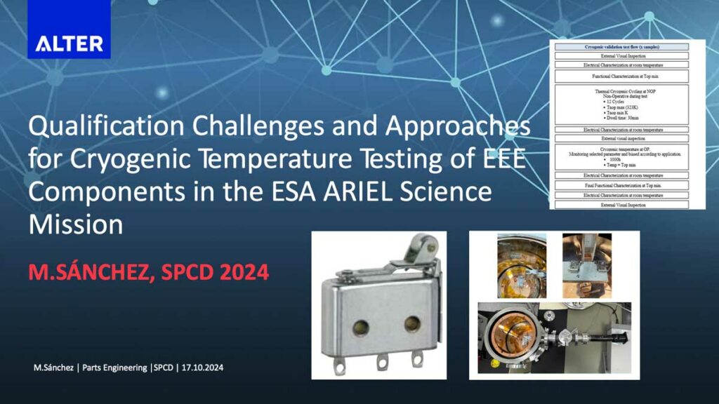
Qualification Challenges and Approaches for Cryogenic Temperature Testing of EEE Components in the ESA ARIEL Science Mission.
Introduction
Space Science instrument missions now require EEE parts that can withstand extreme temperatures, reaching as low as 0 Kelvin. To ensure the reliability of these Passive components, careful selection and testing are necessary.
ALTER, as the Components Procurement Parts Agency for the ESA ARIEL science mission, has collaborated with ESA to review and select EEE components. These components are tested at cryogenic temperatures tailored to each subsystem’s requirements. Most subsystems operate between 29K and 100K.
Of these components, passives include capacitors, resistors, connectors, cables, thermistors, thermal sensors, heaters, and switches. This paper describes the qualification approach, highlighting testing challenges. It includes the testing flow, equipment, and results.
Mission Background And Equipment
Ariel (Atmospheric Remote-sensing Infrared Exoplanet Large-survey) is part of ESA’s Cosmic Vision 2015-2025 plan. It continues tasks from the PLATO mission to identify new exoplanets. Ariel’s main goal is to characterize and study exoplanets individually and in groups, correlating their characteristics to their host stars.
Ariel carries a dedicated payload distributed into a Cold Payload Module (PLM) and a Warm Service Module (SVM). The harness connecting the TCU (Telescope Control Unit) in the SVM to the M2M (M2 pointing mechanism) in the PLM works at different temperatures in different locations. Another notable fact is that equipment like the Active Cooler System (ACS) can reach temperatures as low as 29K.
Testing Candidates And Discussion
- Temperature coverage: Each equipment is under the responsibility of a different user, so their DCLs specify which components are subject to cryogenic temperature conditions. A comprehensive analysis has been performed to select testing candidates based on the temperature values seen by the parts and the most stringent conditions affecting the family. For instance, if a single thermistor is used by two users on the ACS and AIRS equipment, ACS conditions are considered for testing.
- Family coverage: Candidates are selected to provide representative results for all families under study, including connectors, cables, capacitors, resistors, thermistors, flexible heaters, and microswitches.
- Technology corner coverage: From each family/series, the most critical technology-related candidate is selected. For example, from ESCC 4001/023 qualified resistors, the largest size (chip 2010) and highest resistance value (7980 Ω) are chosen.
Many parts, especially connectors and their accessories and cables, will be tested under the same testing plan. This is because the project aims to group parts to reduce test campaigns, significantly lowering the cost and lead time.
Testing Flow
TESTING FLOW
The testing flow agreed within the project is shown in Table 3. The sequence is aimed at addressing the performance of the EEE components at the conditions in which they will operate during the mission.
The Table 3. shows the test flow agreed to be performed on these components.
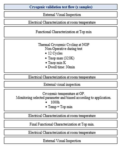
- The 12 cycles between maximum and minimum non-operating temperature range are intended to measure the thermal stress suffered by the component just by being at those temperatures, while the test is performed under no biasing conditions.
- The life test 1000h is designed to measure the fatigue suffered by the parts by working biased at the minimum operating temperature conditions. 1000h is reduced to 500h for Thermistor, Connectors and Cables.
The minimum operating temperature conditions for the equipment are 29K. However, the parts won’t always work at this temperature, but they will work between 29K and 100K for about 2000 cycles during the mission lifetime. To avoid external stress or failures, the 2000 cycles are replaced by a test at 29K for 1000 hours, which is similar to the 2000 cycles.
The testing is performed at ALTER facilities in Madrid, Spain, by experts using a close-loop Helium cryostat. A vacuum feedthrough connects the parts to the measurement equipment for monitoring electrical characteristics.
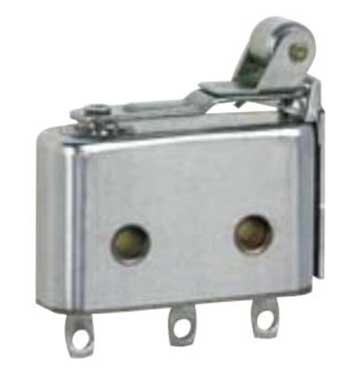
A special case of the parts tested is the microswitch manufactured by PETERCEM (FR) – see Fig.1. It will be used to determine the status of the mechanism at cryogenic temperatures.
The characterization of the microswitches at 40 K involved force-displacement and electrical measurements of contact resistance at room temperature. Samples were placed in the test setup without contact with the switching tool to prevent heat dissipation. After cooling to 40 K, manual movement of the linear feedthrough while monitoring the electrical contacts of the switches was performed. The ON-OFF switching will be repeated 5 times for repeatability. Afterwards, parts will be heated until ambient temperature. Finally, force-displacement and electrical measurement of contact resistance at room temperature will be repeated for comparison.
Testing
Verification at 40K shows the evolution of the temperature monitored during the cooling with the Helium cryostat and the resistance of the NO (Normally Open) and NC (Normally Close) contacts of the two samples under test. Both samples switched properly repetitively at 40K and at room temperature before and after the cryogenic verification.
The resistance measurements were done with 2 wires connection and therefore it includes the wires and feedthrough resistance. An additional verification of the switching capability was performed during the cooling phase at 70K approximately to verify the correct behaviour of the setup.
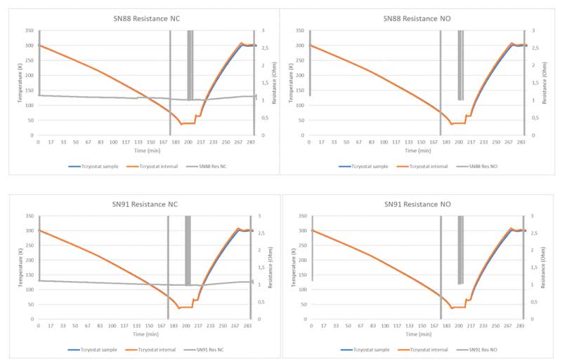
In the case of both samples, the NC contacts line starts at a certain value (around 1Ω) and rises to infinity when switching. On the other hand, for the NO contacts, the graphs show the opposite, starting on infinity values and going down to around 1Ω when switching. For practical purposes, the resistance scale on the graphs has been limited to 3Ω, although the data obtained shows correct values.
In relation to the resistance value obtained when contacts are closed, it is of interest to note that it is way higher than 50 mΩ, (contact resistance of the microswitch), which is in line to the fact that the measurements also account for the feedthrough and the cables resistance.
The force-displacement values of each of the microswitches are not affected by the temperature, so the results obtained are quite similar between the initial and the final measurements, with little deviation. In relation to the electrical characterization at 40K, the resistance values stay reasonably steady during the whole period of the test, even in the cryogenic temperature range, only being affected by the switching cycles.
Conclusion
- Test performed cannot substitute a deeper evaluation (qualification to be performed). Nevertheless, samples do not show external flaws or cracks after testing.
- Samples can switch on and off at 40K. Mechanical parameters are not widely affected by the temperature decrease and recovery.
- Main challenges faced are due to Schedule constraints:
- On one side: huge number of parts affected by cryogenic temperatures: necessary to study thoroughly any change in Users’ DCLs in order to check all families/technologies remain covered by testing.
- On the other side: 1000h life test supposes a long testing time. To speed-up testing, the use of a second cryostat working in parallel is underapproval.
- Next Steps: Qualification testing flow on this part and rest of candidates.
- Possible small database of behaviour of European EEE passive parts to cryogenic temperatures.
Read the full paper here:

