
NASA released an extensive 70pages report on low voltage ceramic capacitors MLCC cracks issues published on nepp.nasa.gov. The report in detail describes manufacturing process of MLCC types, provide comparative analyses of MIL, NASA vs ESA vs JAXA specifications, explains qualification procedures and cracking risk issues including degradation and failure mechanisms. The final section recommends methods for workmanship and failure detection.
Source: NASA Goddard Space Flight Center report. Report prepared by Alexander Teverovsky, ASRC Federal Space and Defense
The excerpt is published herein at EPCI website under author’s permission.
Introduction
Cracking remains the major reason of failures in multilayer ceramic capacitors (MLCCs) used in space electronics. Due to a tight quality control of space-grade components, the probability that as manufactured capacitors have cracks is relatively low, and cracking is often occurs during assembly, handling and the following testing of the systems.
Majority of capacitors with cracks are revealed during the integration and testing period, but although extremely rarely, defective parts remain undetected and result in failures during the mission. Manual soldering and rework that are often used during low volume production of circuit boards for space aggravate this situation.
Although failures of MLCCs are often attributed to the post-manufacturing stresses, in many cases they are due to a combination of certain deviations in the manufacturing processes that result in hidden defects in the parts and excessive stresses during assembly and use. This report gives an overview of design, manufacturing and testing processes of MLCCs focusing on elements related to cracking problems.
The existing and new screening and qualification procedures and techniques are briefly described and assessed by their effectiveness in revealing cracks. The capability of different test methods to simulate stresses resulting in cracking, mechanisms of failures in capacitors with cracks, and possible methods of selecting capacitors the most robust to manual soldering stresses are discussed.
MLCCs in hi-rel and space systems
Compared to commercial, hi-rel and especially space systems are using a more conservative approach for selection of components and a substantial proportion of MLCCs used in high-level space projects has size 1206 and larger. However, the trend for using smaller size, high volumetric efficiency capacitors exists, and the use of advanced technology capacitors in newly design space instruments and systems is increasing.
Considering the amount of MLCCs used, the overall probability of their failures is extremely low. Still, because they are failing typically in a short circuit mode, failures might cause catastrophic consequences to the whole system, cease some system functions, or result in intermittent failures that can be misgauged as a software problem. Capacitors are typically responsible for up to 30% of the field failures in commercial systems, and until recently, approximately half of these failures were due to cracking in the parts.
The proportion of MLCCs in space instruments is similar to commercial assemblies and varies from 10 to 20% of all electronic components. According to Paumanok Publications, the cost of capacitors procured by aerospace industry is 73% of the whole cost of passive components. The major vendors that produce 57% of all capacitors procured by aerospace companies are AVX Corporation, Vishay Intertechnology, and Kemet Electronics. Japanese vendors who dominate commercial market (TDK Corporation, Murata Manufacturing, Matsushita, Rubycon) do not sell directly to the global defense markets; however, capacitors produced in Japan find their way into defense electronics through distribution.
Cracks origin
Cracks and delamination in MLCCs might originate from manufacturing processes or be introduced during assembly or the following handling and testing of the boards (flex cracks or thermal shock cracks). Examples of different types of cracks are shown in Figure below:

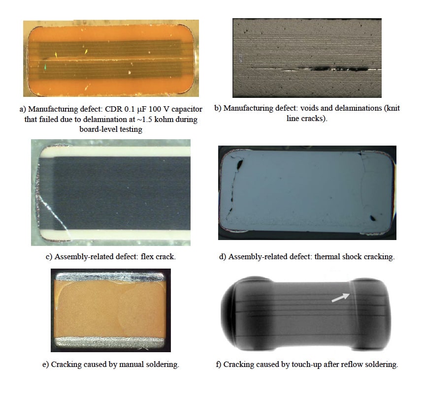
Most cracks in MLCCs caused by deformation of PWBs during assembly, handling or testing are initiated at the surface close to the terminal areas of capacitors. These cracks might affect reliability of the parts if they are reaching active area of capacitors and cross opposite electrodes. For these reasons, parts with thicker cover plates and larger end margins are more resilient to cracking-related failures.
Cracking Issues Mitigation
To mitigate risks of cracking-related failures, special designs of MLCCs have been developed. For low capacitance values, KEMET, similar to other manufacturers, offers the Floating Electrode (FE-CAP) capacitors. This design is also known as a Serial Cap design. For mid capacitance values, the Open Mode solution that has enlarged end margins that create safe zones on both ends of the capacitor. Other manufacturers, e.g. TDK are using similar design approaches to reduce failures caused by cracking (see figure below).

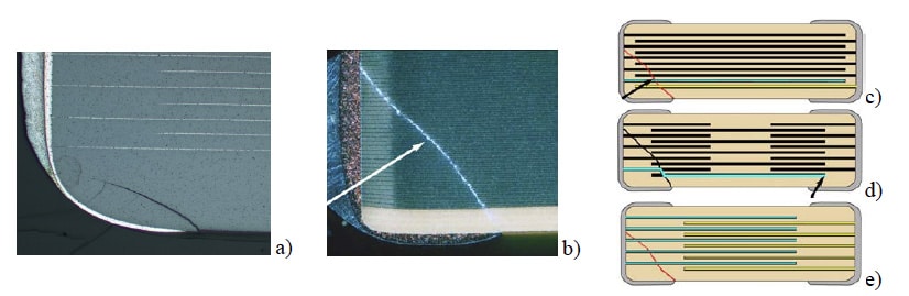
Soldering related cracks in MLCCs and schematics of a standard part (c), floating electrode capacitor (d), and Open Mode design (e) Yellow and blue lines in (c-e) represent electrodes with different polarity.
Various designs of MLCCs that have been suggested by manufacturers to decrease the probability of flex cracking can be summarize as following:
- Flexible termination. Application of relatively soft and/or tear-away termination layers made of conductive polymers reduces the stress in ceramic and restricts flex cracks within a safe zone away from the body of the MLCC.
- Fail open design. End margins are widened, so if a crack occurs, it does not cross electrodes with opposite polarity, and thus prevents short-circuit failures.
- Floating electrodes. Two capacitors connected in series within an individual case size, so the probability of shorting cracks is reduced substantially.
- Clip-on lead frame. Attachment of J-shaped leads mechanically decouples the MLCC from the PWB and allows for some stress relief.

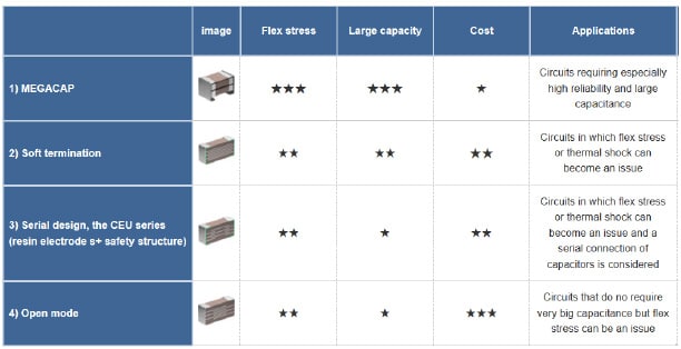
MLCC designs with flex crack countermeasures used by TDK.
A combination of floating electrode and flex termination design (e.g. a TDK Dual-Fail-Safe, Mega Cap design [39]) allows to reduce the risk of failures even further. This design has been proven highly reliable, and no cracks developed in the parts after 3000 thermal shock cycles.
Obviously, the cost of improved reliability of MLCCs with increased margins or floating electrodes is a lesser volumetric efficiency. For this reason, flex termination is likely the most efficient cracking mitigating measure.
Testing and quality assurance
Approaches for quality assurance of commercial and military capacitors are substantially different. Quality assurance of mass production commercial capacitors is based on the build-in-design approach and extensive use of the Statistical Process Control (SPC) system. Military specifications also require SPC system to be used, but it is not considered a major element of QA, and inability to make in-process improvements reduces substantially its efficiency. Instead, QA for military capacitors is based on extensive inspections and testing of the parts. As stated by Dan Friedlander “SPC targets failures prevention, burn-in (testing) targets failures detection”.
Requirements for screening of low-voltage MLCCs by different standards

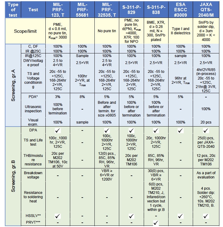
*PDA = percent defectives allowable
**HSSLV = humidity steady state low voltage test that is carried out at 1.3V for 240h at +85°C and 85%RH, typically using 12 samples.
***PRVT = Process Reliability Verification Test.
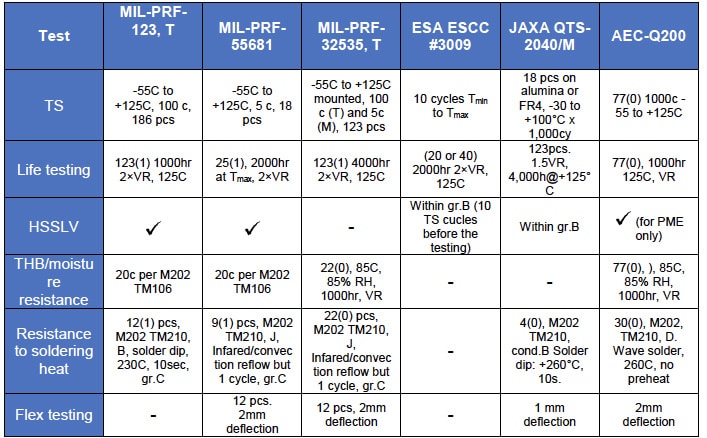
Requirements for MLCC qualification testing by different standards

Failures of MLCCs with cracks are commonly explained by moisture sorption that increases conductivity along the surface of the crack or causes electrochemical migration (ECM) of electrode materials and formation of shorting metal dendrites. Silver that is used in PME capacitors is a metal most susceptible to ECM.
Migration of silver can be observed at voltages as low as 0.4 V and relative humidity down to ~ 40% RH, which is the reason of so-called low-voltage failure phenomena in capacitors.
Much less is known about ECM in BME capacitors with internal electrodes made of nickel, which is often considered as a non-migrating metal. In the absence of moisture in environments, e.g. during life testing at 125 ºC or at low temperatures in vacuum, degradation and failures in capacitors with cracks might also happen, but the mechanism of the process is less obvious compared to humid environments.
Capillary condensation can fill tiny cracks with water even at relatively low level of humidity in environments and remain trapped in the crack even after several days in dry conditions with potential of dendrites formation. Results show that the presence of condensed water in relatively wide cracks can result in formation of shorting dendrites within a few minutes even at voltages below 1.5 V.
Formation of dendrites bridging electrodes and their blowing after short circuit might explain intermittent behavior of failures in MLCCs in humid environments. When electrodes are bridged by a tiny dendrite, this blowing might clear the short, after which the process repeats. However, when a relatively large dendrite is formed, the resistance of the short is less and the dissipated power is larger. This might result in a micro explosion creating a more severe damage to the structure of capacitors and cause melting of ceramic and catastrophic failures (see an example in Figure below). It is also possible that during such an event the melted metal will be forced to fill out other areas of the crack that during cross-sectioning might be misjudged as metal migration.

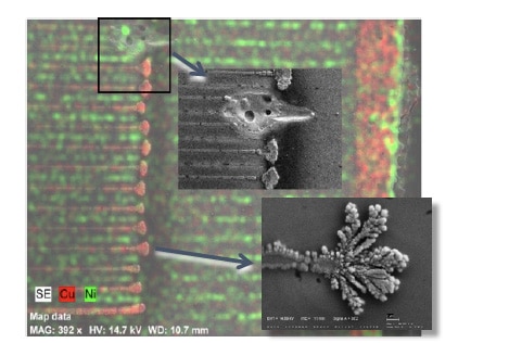
An example of a catastrophic failure caused by copper dendrites growth on a surface of a BME, 1 μF 50 V, case size 1812, capacitor. These dendrites grew for 5 min at 3 V, 95% RH, but the short circuit failure occurred when a rated voltage was applied after the testing. An overall SEM image is overlapped with EDS mapping and the top insert shows the area of a blown dendrite resulted in damage of ceramic, and the bottom shows a clos-up of a copper dendrite.
In a simplified form, processes of ECM on the surface of BME and PME capacitors that result in dendrite growth at cathode electrodes, formation of precipitations between the opposite electrodes, or formation of deposits at anode electrodes are shown in next figure below.
The process of dendrite growth occurs in three-steps:
- anodic dissolution of metal ions
- migration of ions along the surface
- deposition at the cathode.

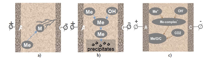
Simplified schematic of electrochemical processes in MLCCs: cathode dendrites growth (a), formation of precipitations (b), formation of anode deposits (c).
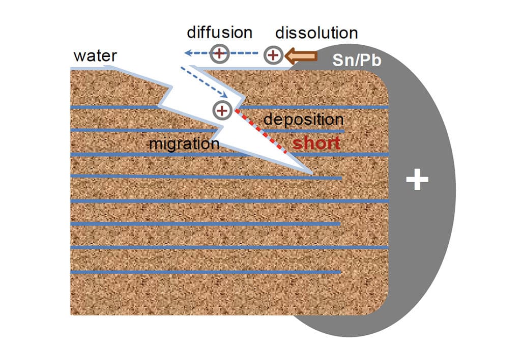
Due to a high susceptibility of metals used in terminations (Cu, Sn, Pb, Ag) to electromigration, generation of ions by the anodic dissolution and their diffusion from terminations along the moisture absorbed layer on the surface of MLCCs can cause failures in both types, PME and BME capacitors. This mechanism might prevail over ECM of internal electrodes in BME capacitors, whereas silver migration originated either from terminations or internal electrodes and formation of conductive oxides deposits is prevailing in PME capacitors.

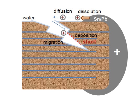
Schematic of failures in MLCCs with cracks caused by migration of ions that are anodically dissolved from terminations.
Considering that cracks might grow with time in the presence of moisture in environments, it might take months and even years of operation at normal conditions to form a short. Incresed humidity, temperature and voltage would accelerate the degradation process substantially. However, due to the difficulties in predicting behavior of cracks and complexity of the ECM processes involved, there is no reliable models to assess acceleration facors for cracking related failures.
Derating, that is one of the major means to increase reliability of components during operation, might be not effective to mitigate cracking related failures. For example, decreasing temperature of operation might have an adverse effect due to the associated increase of relative humidity. Because ECM can occur at very low voltages (below 1.5 V), reduction of voltage does not eliminates the risk of electrical failures.
Operation in dry environments after the parts with cracks have been exposed to humid conditions might not eliminate the risks of failures. For space electronic modules stored or operating at the ground, a gradual diffusion of water molecules inside a capacitor is possible, and the presence of moisture on the surface of cracks and associated degradation of IR can be observed with time of operation at normal conditions.
Degradation in dry environments
Due to a reducing atmosphere during sintering of BME capacitors, the concentration of charged oxygen vacancies (VO++ ) in the ceramic is increased, and the mechanism of degradation during life testing is attributed to migration and accumulation of VO++ at the grain boundaries and metal/ceramic interfaces. This causes decreasing of the energy barriers and increasing of leakage currents by enhanced electron injection according to the Schottky mechanism. For this reason, BME capacitors are much more susceptible to wear-out failures compared to PME capacitors.
Improvements in materials and process control reduced degradation in BME MLCCs substantially, and currently, the inception of the intrinsic wear-out failures became much greater than the mission duration in most high-reliability applications. However, in capacitors with defects degradation processes might accelerate substantially and cause infant mortality (IM) failures.
Special cases of MLCC cracking during manufacturing, assembly, and testing
Common reasons for cracking are associated with:
- stresses during manual soldering, rework, or touch-up to improve appearance of the fillets
- flex bending of the boards during depanelization, handling, mounting, or vibration testing
- temperature cycling of MLCCs soldered onto PWBs
- excessive power during ultrasonic cleaning of the assembled boards.
Revealing cracks
Commonly used techniques to detect cracks include external visual examination, ultrasonic inspection, electrical measurements of capacitance, dissipation factors and IR. These techniques have been used for screening and qualification in military and space specifications and have been discussed in previous sections. It has been shown that they have a limited capability in detecting small cracks in MLCCs, are used mostly to reveal defects created during manufacturing and cannot be relied on to reliably detect damage caused by soldering and post-soldering stresses.
The most common technique to reveal cracks and delaminations is by ultrasonic microscopy that can reveal gaps even as small as ~ 0.1 μm. Until recently, this technique could be applied to horizontal cracks only, but Sonoscan has developed a method that images cracks and delaminations in unmounted MLCCs, regardless of their direction.
Although the latest development in X-ray imaging, especially using computer tomography 3D or CT-scan imaging system, have been used successfully in revealing flex cracking in assembled large size (1812) capacitors, more work has to be done to assess its sensitivity for smaller size capacitors with cracks caused by soldering.
Cracking caused by manual soldering
Due to the process variations and dependence on operator skills, possible formation of significant temperature gradients, and deviations in the amount of solder, all manufacturers strongly discourage the use of hand soldering for MLCCs. However, due to the low volume production manual soldering is a common process for space electronic assemblies and hybrid microcircuits. In some cases, large size capacitors cannot be positioned using pick-and-place tools, and have to be soldered manually. In addition, high cost of the boards makes rework necessary in case of failures.
The risk of cracking during hand-soldering is increasing with the size of capacitors. The workmanship requirements are based on decades of industry practice and studies, are well-developed and documented. However, procedures that would allow selection of the most robust to manual soldering capacitors has not been sufficiently developed yet.
Conclusion
High-temperature manufacturing processes and materials with different CTEs that are used in MLCCs result in significant built-in mechanical stresses. Deviations from the optimal conditions and some anomalies in the manufacturing process might form hidden defects and reduce the strength of the parts. Additional thermo-mechanical stresses associated with soldering and post-soldering handling of the assemblies can increase stresses to the level sufficient for cracking. These cracks might not affect performance of the system initially, but result in failures with time of operation.
The existing military and space specifications are focused mostly on the quality of as build capacitors and do not address properly effects of soldering and post soldering stresses. Improvements in the existing qualification procedures and using tests that would reflect adequately environmental stresses experienced by capacitors after assembly is necessary to reduce risks of failures during applications.
In spite of substantial efforts that have been made to develop methods for revealing cracks in MLCCs after soldering, none is universal and can detect defective parts reliably.
Replacement of large size PME capacitors with a smaller size, thin dielectric BME capacitors with flexible terminations might reduce risks of cracking and failures in space systems.
The probability of cracking caused by manual soldering depends on the level of external stresses that is controlled by the workmanship and the robustness of MLCCs that depends on the level of built-in stresses, presence of defects and mechanical strength, and is lot-related. To mitigate risks of manual soldering and reduce the probability of cracking-related failures both, a tighter workmanship control and selection of parts robust against manual soldering stresses is necessary. Procedures to select MLCCs most resilient to manual soldering are suggested.
download the full report in pdf with more details, insights, figures and references from the nepp.nasa.gov website here.

