
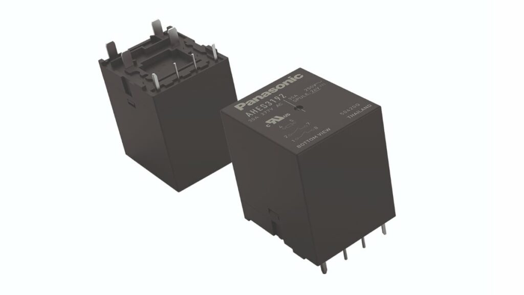
Panasonic’s new HE‑S SC relay family is a compact PCB relay solution designed as the main switching element in next‑generation single‑phase EV charging wallboxes.
It combines high short‑circuit capability with low coil power and integrated mirror contact options to help designers meet upcoming IEC 62955 requirements while limiting size, cost and energy consumption.
Key features and benefits
- High short‑circuit capability with Ip up to 1.85 kA and I²t up to 4.5 kA²s, supporting future European short‑circuit test requirements in IEC 62955 for single‑phase EV charging.
- Contact configuration options HE‑S SC 2a (two normally open contacts) and HE‑S SC 2a1b (two normally open plus one normally closed mirror contact) for flexible system architectures.
- Each NO contact rated for switching currents up to 40 A at ambient temperatures as high as +70 °C according to the manufacturer datasheet, enabling robust operation in thermally constrained wallbox enclosures.
- Sophisticated thermal design and compact form factor suited for direct PCB integration, reducing the need for bulky external contactors or switching assemblies in single‑phase chargers.
- Very low coil holding power of approximately 400 mW, improving overall energy efficiency in standby and active operation of EV wallboxes.
- Integrated mirror contact in the 2a1b version compliant with IEC 60947‑4‑1 for safe contact monitoring and functional safety diagnostics.
- PCB‑mount design that supports reduced system size, simplified assembly processes and lower material cost for wallbox manufacturers targeting competitive price points.
Typical applications
The Panasonic HE‑S SC relay series targets single‑phase EV charging and residential or light commercial wallbox segments where compactness, safety and compliance with evolving European standards are critical.
Typical use cases include:
- AC wallboxes for private residential charging in markets with predominantly single‑phase infrastructure, such as the United Kingdom and parts of Italy and Spain.
- Single‑phase EV charge points in small commercial premises or shared residential parking where PCB‑mounted switching is preferred over large DIN‑rail contactors.
- Integrated charging modules in home energy management systems, where PCB space is limited and direct relay integration simplifies mechanical design.
- Retrofit or upgrade solutions for existing single‑phase wallboxes that must be brought into compliance with IEC 62955 short‑circuit requirements ahead of the Q4 2028 deadline.
In many of these applications, replacing a discrete contactor and wiring harness with a PCB‑mounted relay can free space, reduce wiring complexity, and support automated assembly, which is attractive for high‑volume EV wallbox production.
Technical highlights
Short‑circuit performance and standards
The HE‑S SC relays are designed to meet the upcoming short‑circuit test requirements in IEC 62955 that will become mandatory for single‑phase EV charging systems in Europe in Q4 2028. According to Panasonic, the series provides:
- Short‑circuit current capability: Ip=1.85 kAI_p = 1.85\ \text{kA}Ip=1.85 kA (prospective short‑circuit current the relay can withstand during fault conditions).
- Energy let‑through capability: I2t=4.5 kA2sI^2 t = 4.5\ \text{kA}^2 \text{s}I2t=4.5 kA2s, a key parameter for coordination with upstream protective devices.
In practice, these parameters help design engineers ensure that the relay can survive and safely interrupt specified fault events without catastrophic damage, when properly coordinated with breakers or fuses in the installation.
Contact and coil characteristics
- Contact configuration:
- HE‑S SC 2a: two normally open (NO) power contacts.
- HE‑S SC 2a1b: two NO power contacts plus one normally closed (NC) mirror contact for feedback.
- Power contact capability:
- Up to 40 A switching per NO contact at ambient temperatures up to +70 °C, according to the manufacturer’s specification.
- Coil power:
- Low holding power of approximately 400 mW, allowing reduced thermal load and energy consumption in continuous‑on states.
The low coil power is particularly relevant in wallboxes that must maintain relay energization for extended charging sessions; reducing coil losses limits internal temperature rise and improves overall efficiency.
Functional monitoring via mirror contact
For applications requiring contact position monitoring or enhanced safety diagnostics, the HE‑S SC 2a1b variant adds a NC mirror contact:
- The mirror contact is compliant with IEC 60947‑4‑1 and intended for feedback, not for high‑power switching.
- It supports low‑level loads down to 10 mA at 5 V DC, suitable for connection to microcontroller or PLC inputs for status monitoring.
Using a dedicated mirror contact, designers can implement functions such as interlocking, stuck‑contact detection, or verification that the power contacts are in the expected state, which contributes to functional safety concepts in EV charging systems.
Compact PCB‑mount footprint
The HE‑S SC family is designed for direct integration on the wallbox PCB:
- The compact footprint allows the complete switching function (power contacts and monitoring contact) to reside on the main control or power board.
- This reduces the need for wiring harnesses to external contactors and facilitates automated PCB assembly.
For purchasing teams, this form factor can simplify the BOM by consolidating multiple mechanical parts into a single relay component, making cost comparison and sourcing more straightforward.
Example specification overview
The table below summarizes the key differences between the two main HE‑S SC variants based on the information provided by Panasonic.
| Parameter | HE‑S SC 2a | HE‑S SC 2a1b |
|---|---|---|
| Power contacts | 2 × NO | 2 × NO |
| Mirror / feedback contact | None | 1 × NC mirror contact (IEC 60947‑4‑1 compliant) |
| Short‑circuit capability IpI_pIp | 1.85 kA (according to datasheet) | 1.85 kA (according to datasheet) |
| Energy let‑through I2tI^2 tI2t | 4.5 kA²s (according to datasheet) | 4.5 kA²s (according to datasheet) |
| Max current per NO contact | Up to 40 A @ +70 °C ambient | Up to 40 A @ +70 °C ambient |
| Coil holding power | ~400 mW | ~400 mW |
Where exact numerical values beyond those listed above are required, engineers should refer to the detailed manufacturer datasheet rather than relying on general press‑release information.
Design‑in notes for engineers
- Consider upcoming IEC 62955 timing: European short‑circuit requirements for single‑phase EV charging systems will become mandatory in Q4 2028, so selecting a relay already compliant with these tests reduces redesign risk for wallboxes scheduled to ship around or after this date.
- Coordinate short‑circuit parameters: Use the specified IpI_pIp and I2tI^2 tI2t values from the manufacturer datasheet to coordinate the relay with upstream breakers or fuses, ensuring that protective devices clear faults within the relay’s withstand capability.
- Thermal management: Although the relay is specified for up to 40 A per NO contact at +70 °C ambient, PCB layout, copper area, and enclosure ventilation all influence actual operating temperatures. Treat the datasheet ratings as boundary conditions and verify thermal behavior in the specific wallbox design via testing.
- Mirror contact usage: In the HE‑S SC 2a1b variant, route the NC mirror contact to the control electronics through appropriate low‑voltage isolation and filtering. Use this signal to implement safety functions such as detection of welded contacts or confirmation of open/closed states before energizing power circuits.
- Coil drive strategy: The low coil holding power (~400 mW) allows the use of efficient coil‑drive schemes, such as PWM coil economizing or low‑loss drivers, to further reduce thermal stress and energy consumption, but ensure that any modulation complies with the coil’s electrical limits specified in the datasheet.
- PCB creepage and clearance: Given the relay’s role as a mains‑connected switching device in EV wallboxes, verify that PCB layout meets relevant insulation standards. The relay can only deliver its full safety performance when mounted on a board designed with appropriate creepage distances, clearances and tracking resistance.
- System integration and EMC: By integrating the switching function directly on the PCB, designers can optimize trace routing, snubber networks, and EMC countermeasures (such as RC networks or varistors) around the relay contacts. This helps control switching transients and noise in the EV charger power path.
- Future‑proofing product platforms: Using a relay series that already meets upcoming short‑circuit tests allows manufacturers to keep a common hardware platform across multiple European markets, instead of tailoring designs per country as standards tighten.
Source
This article is based on information provided by Panasonic Industry Europe in their official press release announcing the HE‑S SC PCB relay series for single‑phase EV charging systems, supplemented by the manufacturer’s HE relay family overview and related documentation as indicated in the release.
References
- Panasonic Industry Europe – New HE‑S SC relay series offers latest IEC 62955 compliance for next‑generation single‑phase EV charging systems
- Panasonic Industry Europe – HE relay series overview

