








Source: Semiconductor Engineering article
by Ed Sperling and Susan Rambo. Extended lifetimes and advanced-node designs are driving new approaches, but not everything is going smoothly. Reliability is emerging as the top priority across the hottest growth markets for semiconductors, including automotive, industrial and cloud-based computing. But instead of replacing chips every two to four years, some of those devices are expected to survive for up to 20 years, even with higher usage in sometimes extreme environmental conditions.
This shift in priorities has broad ramifications for the entire electronics supply chain, from the purity of materials to the architecture and all the way through verification, manufacturing, test and post-manufacturing verification and monitoring. While performance, power and area (PPA) continue to be critical factors, those factors need to remain consistent throughout the expected lifetime.
There are some new wrinkles in this formula, too. Reliability increasingly is measured by total system reliability, which in many cases involves systems of systems, and it can vary greatly from one region to the next. So while a self-driving car in the United States or Europe may use 5G when it’s available, in China the data is centralized so that 5G system is as critical as the communication system within a car.
In addition, one of the fundamental requirements of ISO 26262 is the ability to fail gracefully. That requires either a redundant system, which doubles the cost of electronics, or the ability to utilize other circuits that were not designed for a particular job. So while an infotainment system, for example, may not be considered critical to safety when it is designed, it may have to perform as well as a critical system in an emergency.
This poses a potential problem, however. According to a 2017 report by J.D. Power, the audio, communications, entertainment and navigation (ACEN) category was the most problematic area in quality complaints. It accounted for 22% of all problems reported. The company noted AECN issues generated the most complaints last year, as well.
In response, automotive OEMs last year began demanding that electronics components last 18 years with zero failures. This is partly due to the fact that consumers are less likely to buy their next car from the same company if there are repeated failures, a problem made worse by the fact that the number of chips and electronic components in cars is rising rapidly. Audi reports about 7,000 semiconductor devices in its high-end models, and it turns out about 4,000 cars every day. A failure in the range of one part per million equals 24 defective cars per day. For BMW, which uses about half as many electronic components but manufactures 10,000 cars every day, that equates to 54 defective cars.
And that’s just for starters, because the amount of electronic content in cars is rising.
“Electronics will account for 35% of the cost of a car soon,” said Michael Schuldenfrei, CTO at Optimal+. “And with autonomous driving coming, by 2030 PWC thinks it will be 50% of the cost of the car. If you think about where the cars are today and where they’re going to be tomorrow, this is a problem.”
It gets worse, too, because real-world data doesn’t exist for many of the components that will be used in vehicles.
“In 1995, the automotive market was using semiconductors at mature nodes,” Schuldenfrei said. “Those semiconductor devices were going into radios or electric windows, which were relatively simple systems. Now, a car needs to have the absolute latest and greatest technology to deliver all of the features that ADAS sensors require. There’s no longer the comfort zone for the automotive industry to know they’re using five-year-old technology, where the failure modes and problems are known. They’re now right at the bleeding edge, and no one knows how stable those technologies really are or what the problems are going to be.”
Other experts agree. “Normally it takes five to six years before you know if there is a problem,” said Jim McLeish, senior quality/reliability consultant manager at Dfr Solutions. “With 5nm to 7nm technology, there is no experience. We don’t know what the variation will be.”
Bringing this problem under control will require an in-depth understanding at both the system and the circuit level, but right now there is not enough data to be able to draw good conclusions about where problems may erupt and why.
“What you actually do with the components is that you use them in the beginning to establish confidence that the device will work in the useful lifetime,” said Gert Jørgensen, senior vice president of sales and marketing for Delta’s ASIC Division. “Then, of course, when they get older, they are aging and they’re wearing out. This is the lifetime of components—all components. In cars we want a higher reliability because it could mean a lot if that device is not working.”
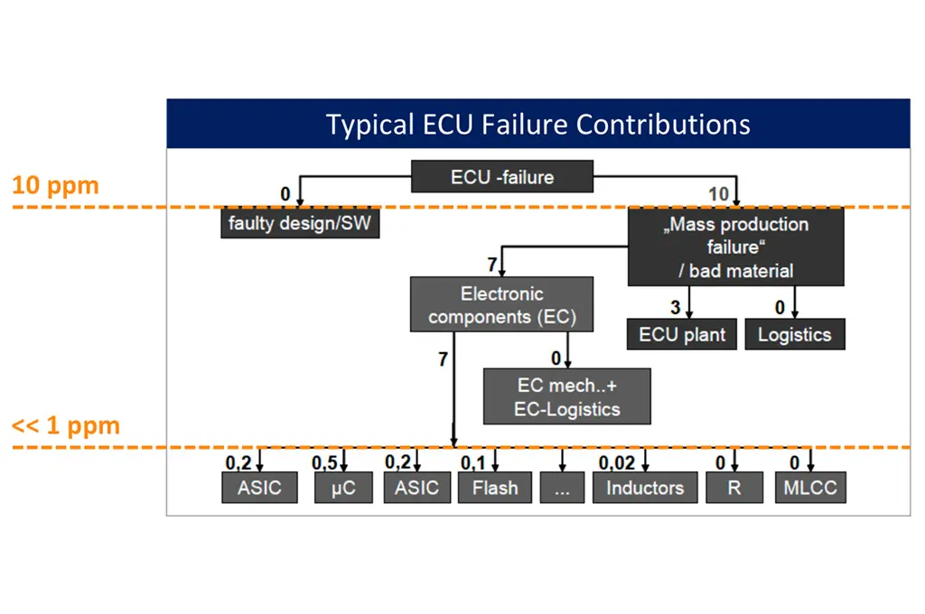
Featured fig. 1: Zero defect challenges. Source: Optimal+
Packaging and test
One of the places where failures are showing up in the automotive world is the standard plastic or ceramic packaging that were largely chosen on the basis of cost, according to numerous sources. This is starting to change, particularly as the automotive industry begins utilizing design tools that have been part of advanced semiconductor design for years. But it also indicates that gaps remain in the expertise of chip companies, which have never worked in the automotive space, and automotive suppliers and OEMs, which have no experience with some of the issues in advanced-node chip design and manufacturing.
Both sides are struggling to close those gaps, and in some cases the solutions aren’t easy to digest.
“What’s happening now is that we’re starting to see things like integrated passive devices being tested in the context of packaging,” said Joey Tun, principal market development manager at National Instruments. “That’s a lot different than in the past, where it was just the processor or the memory. Integrated passives typically were tested before they were put into a package. So things like inductors, capacitors and resistors were fabricated on a wafer and tested at the wafer level. But you can’t measure them accurately on the wafer with high throughput and high volume very easily.”
With automotive and industrial applications, this includes such things as bias temperature instability and impedance. Passives are normally tested individually, but in safety-critical applications or those under harsh conditions they need to be tested in proximity to others to prevent electromechanical coupling. This is well within the capabilities of testing equipment today, but it’s not quick or cheap.
The use of 10/7nm chips in automotive applications is making test more challenging, as well.
“Test times are getting longer,” said Adrian Kwan, business development manager at Advantest. “The tests are getting bigger. There are a lot more transistors in a given area. That requires higher test coverage, and a lot of testers are in the beginning phase of bringing technology up to an acceptable level.”
It also requires more testing in general to deal with more complexity, according to Ira Leventhal, new concept product initiative vice president at Advantest. “This has gotten so complex that things like wafer sort and final test are no longer sufficient. Companies doing advanced chips are relying on system-level test, so now you have to add system-level test insertion as well as deep learning related to hardware and software. And you need sufficient built-in self-test because you can’t predict everything. And with hardware and software, you need functional test to make sure you develop to spec.”
Planning for failures
Despite all of this, some level of failure is inevitable—no matter how stringent the requirements by OEMs and Tier 1 suppliers. Electronics wear out for a variety of reasons. It could be due to a design flaw from a last-minute change, but it also can be caused by a dust particle trapped in a thin film or a gas flow problem when a chip is being etched. And there is plenty of research into what happens when a stray alpha particle hits a 7nm transistor.
“We can rely on stats all day long for manufacturing, but if something is different it can be within the control or spec,” said Julie Ply, quality engineering manager at Brewer Science. “It’s like looking for a needle in a haystack. the first step is getting the data. The next step is understanding what the data means. Then you have to bring that back to the process. Is it within the allowable limits of the process or outside the limits?”
Moreover, it’s not always clear what is a killer defect and what isn’t. Some latent defects may never cause failures, while others that are less obvious can develop into more serious issues under various environmental conditions or excessive vibration, as shown in Fig. 2 below.
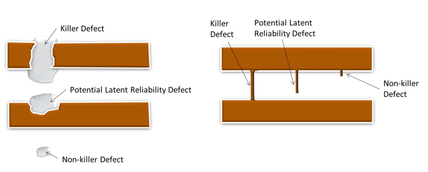 Fig. 2: Potential defect versus killer defect. Source: KLA
While efforts are underway to prevent and identify these effects, there also are efforts to be able deal with problems when they do arise. So in addition to parts being made more reliable, they also have to be easier to replace.
“When you get to the time in their life when electronic control units begin wearing out, that’s going to be problematic,” said Jay Rathert, senior director of strategic collaborations at KLA. “Plus, you have the weight with all of the cable harnesses. But if you can get rid of that and network the actuators to these domain controllers, if they wear out you can swap them out like a laptop. On top of that, the software is simpler.”
Adding to the complexity, different technologies have different parameters that can accelerate aging.
“One acceleration factor is temperature,” said Delta’s Jørgensen. “Another exploration factor is voltage. If a device is assigned to work 12 volts—that is a car battery normally—and it then worked at 24, it is harder for the device to work at 24. You also have different parameters like humidity, voltage, temperature, mechanical shock, which are acceleration factors. And by that, you then simulate lifetime. Now you have the problem—how much do you accelerate its life? What you want to simulate is, of course, around 20 years lifetime in a car. And you want to do it fast, so you get a result normally after three months. You can calculate if you want to see one failure in 20 years. If if you want to see one failure within one month, then a lot of components are used. If you want to see one failure in 20 years, you can add let’s say more components and then you get more operational hours. If you want to simulate that one device has a failure in 20 years, you take maybe 1,000 devices and run them for one hour. That is 1,000 operational hours. That’s why you take out more components and make lifetime testing, so that it happens faster, because what you actually want is to demonstrate how many failures you have in number of operational hours. That is called FIT. One failure in 109 hour is defined as one FIT.”
Jørgensen noted that different automotive levels have different failure in time quality measures. “A consumer level will probably have a 100 FIT quality level, while safety-critical maybe will have 0.1 FIT. You have to simulate lifetime depending on the classification of the device. There are also electronic devices in a car that are not safety-critical, like the electronics to control battery charging. Next you simulate that your device lives up to these different quality levels. To calculate what effect the different acceleration factors gives, you use the Arrhenius equation.”
Conclusion
In the end, no one is quite sure how well this will all work. There are an enormous number of variables in a car, and there are many variables in designing chips at advanced nodes, from process variation to minute defects. The key is to understand and quantify those variables, and then to use all of the knowledge accumulated on both sides to be able to predict flaws and find killer defects.
“Safety-critical applications will require additional testing as we better understand the defect mechanisms,” said Anil Bhalla, senior manager at Astronics. “The industry is assuming this will work based on early trials. More trials on a broader scale will support the gradual roll-out of this new technology. The economics of autonomous driving is motivating the entire semiconductor ecosystem to evolve during this transition.”
At this point, it appears there is still a long way to go.