


Resistors in power and signal circuits rarely see pure DC; they are often stressed by pulses, surges and elevated temperatures that can dramatically reduce lifetime if not handled correctly. This guide provides a practical, step‑by‑step methodology to select and derate resistors for reliable operation under pulse, power and voltage stress.
Key Takeaways
- Key concepts: The article explains pulse types, overload factors, limiting voltage, critical resistance and temperature derating, with equations linking pulse parameters to safe resistor operation.
- Datasheet‑driven design: Shows how to use manufacturer pulse, energy and derating curves together with rated power and limiting voltage to validate both single and repetitive pulses.
- Structured procedure: Provides a seven‑step flow from defining the environment and selecting technology to voltage/power checks, pulse‑energy verification, thermal/layout review and qualification testing.
- Technology choices: Compares carbon film, metal film, thick‑film chip, wirewound and dedicated surge resistors, highlighting which are best suited for high‑pulse and high‑energy applications.
- Practical implementation: Covers series/parallel networks, typical application scenarios (inrush, snubbers, automotive surges) and common failure modes, with mitigation strategies via derating, layout and testing.
Basic Concepts and Definitions
Pulse‑loaded resistors must satisfy several simultaneous limits: average power, instantaneous voltage, peak current and pulse energy. Reliable design therefore starts from a clear definition of the waveform and environment, followed by comparison to resistor limits given in standards and datasheets.
Periodic pulse loads
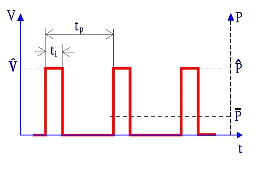
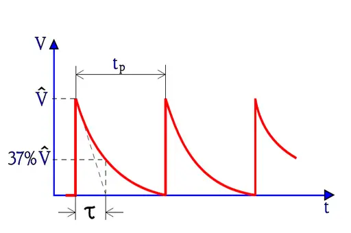
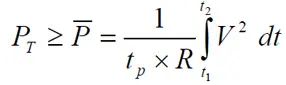
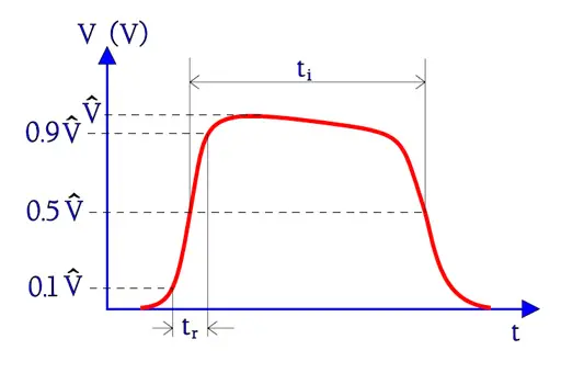
Figures 1. and 2. show two typical types of pulses, rectangular ones and exponential ones. The theoretical square pulse has in practice sloping fronts and rear edges. The definitions of times and voltages of a square pulse are shown in Figure 3. With definitions from Figure 1., 2. and 3., the following general conditions apply.
here:
PT = permissible power at the ambient temperature T
P¯= mean power in the pulse train.
1/tp = pulse repetition frequency.
ti = pulse width t2 – t1.
R = rated resistance.
V = instantaneous voltage.
tr = rise time (Fig 3.)
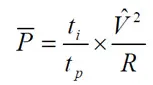
For rectangular pulses the following equation applies:
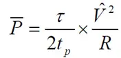
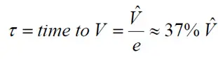
and for exponential pulses, according to Figure 2.;
One talks in this connection about
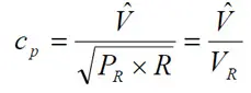
1. Power overload factor
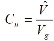
2. Voltage overload factor
3. Current overload factor
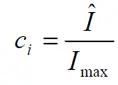
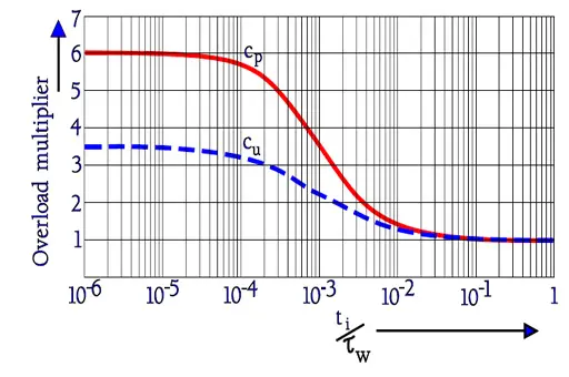
Figure 4. shows the overload factors cp and cu for carbon film resistors.
Pulse loads in single pulses or pulse trains, with a permissible mean power as shown in Equation [2] or [3], always have to take into consideration the voltage strength.
In order to verify the pulse capability certain standard tests are outlined by the IEC 60115, for example, the following suggested data:
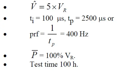
Single Pulses
Sometimes it is necessary to load the resistor with a single pulse (that possibly may be repeated after so long time that a possible heating can be neglected). Certain standardized tests for film resistors as outlined in appendices to IEC 60115 give us some useful basics for comparison. Two pulse shapes are defined: 1.2/50 and 10/700. The figures mean rise time tr/pulse time ti according to definition in Figure 3. and are expressed in microseconds.
The test is performed with a successively increased voltage expressed in multipliers of the limiting voltage Vg until the resistance changes exceed specified values, usually the maximum change during a 1000 hrs life test. (The limiting voltage Vg corresponds to the maximum field strength that the resistor construction can withstand. See figure and legend under 2.). The test follows the description in Table 1.
| Pulse shape tr/ti (μs) | Multiples of Vg | Least pulse distance (s) | Number of pulses |
| 1.2/50 | 10 | 12 | 5 |
| 1.2/50 | 15 | 12 | 5 |
| 1.2/50 | 20 | 12 | 5 |
| 10/700 | 2…6 | 60 | 10 |
The following comparative figure for single power pulses may serve as a guidance for comparison of standard designs in different materials, provided the resistance value doesn’t cause the voltage in the overload factor to exceed cu (Equation [4]). We choose as a reference power pulses with the duration 10 ms. Comparison between materials gives
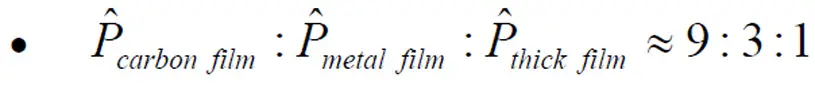
Note, however, that in the lower resistance range thick films may be more resistive to pulses than corresponding metal films.
If we compare the effect from power pulses of different magnitude applied on a certain design we get

We repeat that the stated ratios are approximate. What recommended pulse power, Pˆ, the resistor design can stand has to be read from the manufacturer’s technical information and diagrams and “possible” pulse power has to be verified by tests on chosen resistor type and manufacture.
Pulse terminology
For design purposes we distinguish:
- Repetitive pulse trains, where pulses repeat with a defined period and the resistor temperature does not fully return to ambient between pulses.
- Single or isolated pulses, where the time between events is long compared to the thermal time constant and self‑heating from previous pulses can be neglected.
Key timing parameters are:
- Pulse width ti: time between the 90% rising and 90% falling points or other specified levels (e.g. according to IEC pulse definitions).
- Rise time tr: interval between 10% and 90% of the pulse amplitude for a step‑like waveform.
- Pulse period tp: time between the start of consecutive pulses; its inverse is the pulse repetition frequency.
Average power in pulse trains
For a periodic pulse train the mean power over one period must be less than the permissible continuous power at the actual ambient or body temperature. For rectangular pulses of amplitude V across a resistance , with duty cycle , the average power is:For exponential pulses (for example, RC discharge), equivalent expressions exist where power depends on the exponential decay constant; these are often provided in resistor standards and manufacturer application notes.
Overload Factors: Power, Voltage and Current
It is convenient to normalize pulse stress to the resistor’s rated values using overload factors. These dimensionless ratios allow direct comparison between different resistor technologies and the generic graphs used in standards.
Common overload factors are:
- Power overload factor : ratio of allowed pulse voltage to limiting voltage, often expressed so that pulse power factor is .
- Voltage overload factor : ratio of applied pulse voltage to rated or limiting voltage.
- Current overload factor: ratio of applied pulse current to rated current, derived similarly from the power equations.
For a given resistor technology, standardized curves show how and depend on normalized pulse width , where is a thermal time constant of the resistor element. For short pulses the resistor can withstand a high instantaneous power, but as pulse length increases the permissible overload factor decreases toward the continuous rating.
Material dependence
Pulse capability is strongly technology‑dependent:
- Carbon film: comparatively high pulse capability thanks to thicker films and higher thermal mass.
- Metal film: lower pulse overload than carbon film of the same resistance due to thinner film and higher current density.
- Thick film / metal glaze: generally poorer pulse capability than metal film at mid/high resistance, but can be better at low resistance where conductive content is higher.
- Wirewound: usually highest pulse and overload capability due to robust wire element and mass, often used for surge and high‑energy applications.
Standards such as IEC 60115 provide reference data for pulse testing of film resistors, including specific surge waveforms.
Voltage Limits, Critical Resistance and Limiting Voltage
Even if average and pulse power are within limits, the resistor may fail due to excessive electric field and internal flashover. Designers must therefore check both power and voltage limits.
Resistor series usually specify:
- Rated power at a reference temperature (e.g. 70 °C).
- Limiting voltage , the maximum permissible voltage independent of resistance value.
If we plot voltage and power versus resistance on linear axes:
- For low and medium resistance values, power is constant at ; voltage increases as
- At a certain resistance , the voltage curve reaches ; this defines the critical resistance.
- Above , voltage is capped at and power decreases as .
Any pulse design that implies a peak voltage above at the chosen resistance is unacceptable, regardless of power or energy considerations.
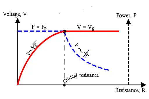
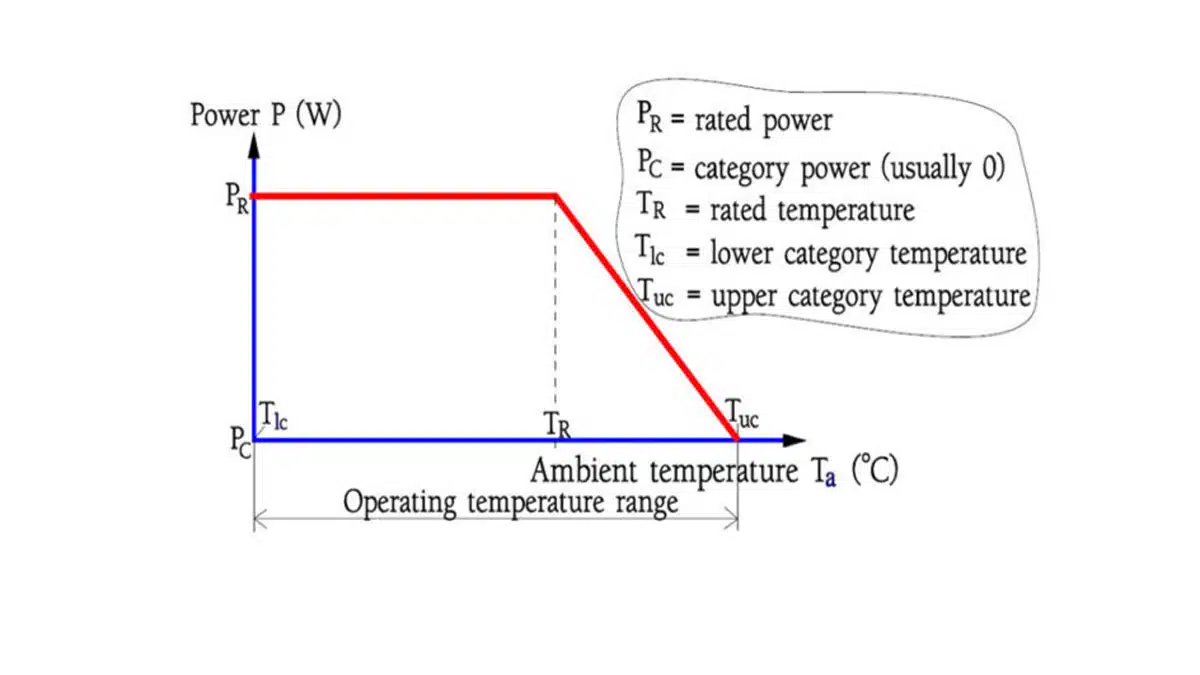
Vg = limiting voltage. PR = rated power
Interaction with pulse overload
Pulse overload factors must be applied with respect to both power and voltage:
- Shorter pulses allow higher , meaning higher peak power, but this comes with a corresponding increase in peak voltage when applied at a fixed resistance.
- It is therefore incorrect to scale pulse power linearly with pulse duration without checking that the resulting voltage does not exceed .
Manufacturers often stop increasing recommended pulse power beyond a certain short pulse width because further increases would require voltages above the limiting field strength.
Temperature Derating of Power
Power rating is specified at a reference ambient, but actual permissible power decreases with rising temperature to keep internal hotspot temperatures within material limits. Proper derating is critical in high‑temperature environments or when significant self‑heating occurs from continuous or frequent pulses.
Standard derating curves
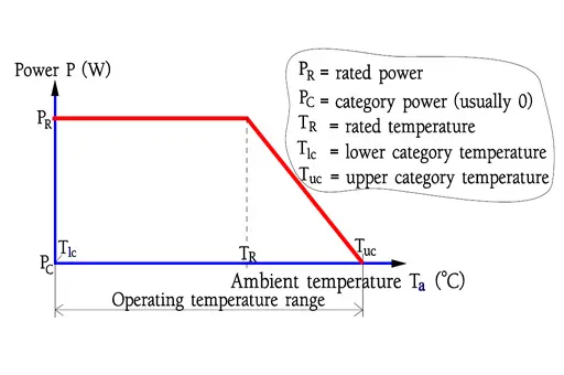
Typical derating curves define:
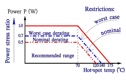
- Rated power valid from 0 °C to a reference temperature (often 70 °C).
- Linear derating from at 70 °C to 0 W at the upper category temperature (for example 155 °C or 175 °C depending on resistor type).
Military and high‑reliability standards may impose additional derating, e.g. using only 50% of the commercial power rating at 70 °C, reducing linearly to zero at the same upper category temperature.
For design:
- Determine the maximum expected ambient temperature and PCB self‑heating.
- Use the derating curve to find the permissible continuous power at this temperature.
- Ensure the average power from pulse loading does not exceed this derated value.
This temperature‑derated power is the baseline used in pulse overload and energy calculations.
Energy‑Based View and Thermal Time Constant
For many surge and inrush cases, single‑pulse energy, rather than average power, is the dominant stress. Considering pulse energy makes it easier to compare application requirements with resistor “Joule ratings” provided by manufacturers.
Pulse energy is defined as:For typical waveforms:
- Rectangular pulse:
- Exponential decay: can be expressed in terms of initial voltage and the RC time constant of the discharge.
Manufacturers often specify the maximum energy that can be absorbed for a given pulse width or number of pulses without exceeding a specified resistance change or failure probability.
Thermal time constant and repetition
The resistor thermal time constant τth defines how quickly it can dissipate heat into its environment. For pulses:
- If and the time between pulses is long compared to , the resistor behaves as a lumped thermal mass, and single‑pulse energy limits dominate.
- If pulses are frequent relative to , average power and cumulative heating become critical; energy per pulse is still relevant, but must be combined with average power considerations.
Datasheet graphs that plot permissible pulse energy versus pulse duration implicitly include both electrical and thermal limits for a given package.
Using Datasheet Pulse and Derating Curves
The most reliable way to check pulse capability is to use the manufacturer’s datasheet curves together with the equations above. Different vendors may express limits as power, energy or voltage versus pulse width and number of pulses.
Typical datasheet graphs
Common pulse‑related graphs include:
- Permissible pulse power vs pulse duration for single pulses and for a specified number of pulses.
- Permissible pulse voltage vs pulse duration (often normalized to limiting voltage).
- Joule rating vs pulse width.
- Derating curves vs ambient temperature.
Some datasheets also state standard test waveforms such as 1.2/50 µs and 10/700 µs surges aligned with IEC tests.
Reading and applying the curves
Design steps when using such graphs:
- Identify the resistor series, size and technology (e.g. thick‑film chip 1206, metal film axial, wirewound).
- From the datasheet, note PR, Vg, derating curve, and the relevant pulse graphs.
- Convert your application pulse into the same metric used in the graph (power, voltage or energy vs pulse width).
- For repetitive pulses, verify both:
- Average power at ambient does not exceed derated PT.
- Each pulse (or set of pulses) stays below the curve for the corresponding number of pulses.
- For single pulses, treat each event using the single‑pulse curve and appropriate rest time between pulses.
Design Procedure for Pulse‑Loaded Resistors
This chapter proposes a practical, repeatable design flow that you can convert directly into a checklist or design template.
- Step 1: Define electrical and thermal environment
Collect:
Supply voltage, worst‑case tolerances and clamping levels.
Pulse shape (rectangular, exponential, surge waveform), amplitude, rise time and pulse width.
Repetition rate or expected number of pulses over life.
Maximum ambient temperature, enclosure conditions, airflow and PCB area available for heat spreading. - Step 2: Select preliminary resistance value and technology
Based on circuit function, choose:
Nominal resistance and tolerance.
Candidate technologies: carbon film, metal film, thick‑film chip, wirewound or dedicated pulse/surge resistors.
Initial package size based on continuous power requirement (before pulse considerations), using derated power at max ambient.
At this stage, also consider whether special surge or pulse series are needed, particularly for mains and automotive surge events - Step 3: Check voltage limit
With the chosen resistance, calculate peak pulse voltage and compare against limiting voltage:
For rectangular pulse: use the peak applied voltage.
For current‑driven cases, compute .
Ensure does not exceed (or the appropriate multiple of if the datasheet explicitly defines approved surge multiples for specific waveforms).
If the required voltage is too high, consider:
Increasing resistance and splitting into series elements to share voltage.
Selecting a resistor series with higher limiting voltage.
Changing circuit topology to reduce stress. - Step 4: Check average power with temperature derating
Compute average power:
For simple rectangular pulses: .
For more complex waveforms, integrate over a period or use known closed forms.
Then:
Use the derating curve at the worst‑case ambient to find permissible power .
Verify ; otherwise, increase package size, use multiple resistors or improve cooling - Step 5: Check pulse power and/or energy vs datasheet curves
For the critical pulse:
Compute peak power .
Compute pulse energy for the actual waveform.
Compare against datasheet:
If the datasheet provides a pulse power vs duration graph, ensure at your pulse width lies below the curve.
If it provides energy vs duration, ensure your at the pulse width lies below the specified limit.
For repeated pulses, use the graph that corresponds to the number of pulses or pulse train conditions; otherwise, apply a manufacturer‑recommended reduction factor.
If the pulse exceeds limits:
Move to a larger package or series with higher pulse rating.
Use multiple resistors in series or parallel to share voltage, current and energy.
Modify the circuit to limit peak voltage or current (for example, by adding snubber elements). - Step 6: Validate thermal behavior and layout
Translate electrical stress into thermal behaviour:
Estimate temperature rise from average power using datasheet thermal resistance or empirical guidance.
Confirm that combined ambient temperature and self‑heating do not exceed upper category temperature or specified hotspot limits.
Layout considerations:
Provide enough copper area under and around chip resistors to spread heat; large pads and thermal spokes improve cooling.
Avoid placing high‑pulse resistors tightly next to heat‑sensitive components.
For series chains, ensure adequate creepage and clearance between resistors for high‑voltage pulses. - Step 7: Plan qualification tests
For high‑reliability designs:
Perform pulse tests on representative samples using the worst‑case waveform, voltage and energy.
Monitor resistance change before, during and after testing to ensure it stays within the specified drift (often similar to life test limits).
Use standard waveforms such as 1.2/50 µs and 10/700 µs surges when relevant for EMC and surge compliance
Technology‑Specific Pulse Capability
Because pulse limits vary widely by technology and package, it is helpful to understand the qualitative hierarchy.
Carbon and metal film resistors
- Axial leaded carbon film resistors typically exhibit higher admissible pulse load than metal film for the same size and value, especially for short pulses.
- Metal film parts provide better precision, stability and noise but require more conservative pulse derating due to thinner films and higher local current density.
Within a given series, manufacturers may offer “high‑pulse” variants with modified constructions, such as thicker films, larger ceramic bodies or tailored end caps.
Thick‑film chip resistors
- Standard thick‑film chip resistors have modest pulse capability, especially in high‑value ranges where conductive content is low and current crowding occurs in the granular network.
- At low resistance values, thick‑film chips can handle higher current and sometimes match or exceed metal film pulse capability, but voltage gradients must still respect limiting voltage.
For demanding applications, dedicated high‑power or surge‑rated chip series (for example, on AlN substrates) provide improved pulse and power performance at the expense of size or cost.
Wirewound and dedicated surge resistors
- Wirewound resistors are often preferable for high‑energy pulses, load dump and pre‑charge due to their massive resistive element and robust construction.
- Specialized surge resistors may use optimized wirewound or film constructions, molded encapsulation and enhanced creepage distances to withstand standardized surge tests.
These parts are typically characterized with detailed energy and surge specifications tailored to automotive and mains applications.
Series and Parallel Configurations for Pulse Sharing
Splitting stress across multiple resistors can greatly improve pulse capability and reliability when done correctly.
Series connection
Using multiple resistors in series:
- Shares voltage stress across several elements, reducing the voltage per resistor and avoiding exceeding .
- Distributes energy; in symmetrical designs with matched resistors, each element nominally absorbs the same energy, provided voltage division remains equal.
Design considerations:
- Use resistors from the same series and tolerance class to minimize unequal voltage sharing.
- At high voltages or with fast pulses, consider adding small capacitors or resistors to ensure equalization if parasitic capacitances would otherwise cause uneven distribution.
Parallel connection
Parallel resistors share current:
- Peak current divides among branches, reducing instantaneous power and energy per resistor.
- This is beneficial where total resistance is relatively low and conductor cross‑section is the limiting factor.
Design considerations:
- Ensure adequate symmetry in layout so that each branch sees similar parasitic inductance and resistance.
- Verify that the combined resistance fits circuit requirements and that each branch individually meets pulse and power limits.
Application Examples
This section outlines typical use cases and how to approach pulse design qualitatively; you can add numeric examples tailored to your preferred resistor series.
Example 1: Inrush limiting resistor (rectangular pulse train)
An AC‑DC converter may use a series resistor to limit inrush current into a bulk capacitor at power‑on. The resistor experiences:
- High current pulses at turn‑on.
- Elevated steady‑state power from normal operation, especially in universal‑input designs.
Design approach:
- Model or measure the current waveform at turn‑on; derive peak current and pulse width for the worst‑case input and capacitor tolerance.
- Calculate instantaneous power and energy per pulse and compare to the resistor’s single‑pulse and repetitive‑pulse ratings.
- Ensure average power at high ambient meets derated power and verify voltage across the resistor at peak conditions does not exceed .
Example 2: Snubber resistor in flyback converter (exponential pulses)
RC snubbers across transformer windings or switches dissipate energy from leakage inductance and switching transients. The snubber resistor sees:
- Exponential decay pulses at the switching frequency.
- Average power proportional to the product of leakage energy and switching frequency.
Design approach:
- Determine leakage inductance and clamp voltage to estimate energy per switching event.
- Calculate average snubber power as energy per pulse times switching frequency; verify against derated continuous power.
- Check pulse energy and peak voltage against the resistor’s pulse and limiting voltage curves, considering the exponential waveform shape.
Example 3: Automotive load dump and surge protection
Resistors in automotive surge clamps, transient suppression networks or pre‑charge circuits must survive standardized surge pulses such as ISO 7637 and load dump events.
Design approach:
- Use the specified surge waveforms (amplitude and duration) from automotive standards or OEM specs.
- Select resistor technologies and series explicitly rated for automotive surges, often with dedicated surge test data.
- Verify that surge energy, peak power and voltage per pulse remain within the manufacturer’s specified limits, and plan qualification tests with the same standardized waveforms.
Failure Modes Under Pulse Stress
Understanding how resistors fail under pulse overload helps set conservative derating margins.
Typical failure mechanisms
Common failure modes include:
- Internal flashover and arcing when limiting voltage or field strength is exceeded.
- Film cracking, hot‑spot damage or open circuits from excessive local temperature rise.
- Resistance drift beyond tolerance due to microstructural changes, particularly in film and thick‑film resistors.
- Substrate cracking or solder joint fatigue when large temperature swings occur repeatedly.
Mitigation by derating and design
Mitigation strategies:
- Apply conservative derating factors to pulse power and energy, especially for long‑life or safety‑critical applications.
- Choose technologies and packages with appropriate mechanical robustness and thermal mass.
- Use layout and series/parallel arrangements to distribute stress and avoid localized overheating.
- Validate with representative pulse testing rather than relying solely on calculations.
Conclusion
Designing resistors for pulse load, power and voltage derating requires simultaneous consideration of voltage, power, energy, temperature and technology limits, all referenced to real datasheet curves and applicable standards. By following a structured procedure—from defining the pulse and environment, through voltage and power checks, to pulse‑energy verification and layout optimization—engineers can achieve reliable resistor selection for demanding applications such as power inrush, snubbers and automotive surges.
FAQ: Resistor Pulse Load, Power and Voltage Derating
Resistor pulse load describes short‑duration voltage or current stresses that exceed normal steady‑state conditions. Correctly accounting for pulses is essential to avoid overheating, flashover, resistance drift and premature failure in power electronics, snubbers, inrush limiters and automotive surge applications.
For repetitive rectangular pulses, average power is the pulse power multiplied by duty cycle over one period. Designers compare this mean power to the temperature‑derated continuous power rating of the resistor to ensure that self‑heating and ambient conditions remain within safe limits.
Overload factors normalize pulse stress to rated values: the power overload factor relates pulse power to rated power, the voltage overload factor compares pulse voltage to limiting voltage, and the current overload factor compares pulse current to rated current. These dimensionless numbers let engineers use standardized curves to evaluate safe pulse operation across different resistor technologies.
Limiting voltage defines the maximum safe voltage a resistor series can withstand regardless of resistance value. The critical resistance marks the crossover where the design is voltage‑limited rather than power‑limited, and any pulse that exceeds limiting voltage at the chosen resistance is unsafe even if power or energy appear acceptable.
Resistor power ratings apply at a reference ambient temperature and decrease as temperature rises. Designers use derating curves to find the allowable continuous power at the worst‑case ambient and must ensure that the average power from pulse loading stays within this reduced rating for long‑term reliability.
In many surge, inrush and load‑dump scenarios, the dominant stress is the energy of a single pulse rather than its average power contribution. Calculating pulse energy and comparing it to the resistor’s Joule rating helps ensure the component can absorb the required energy without cracking, drifting or open‑circuit failure.
In many surge, inrush and load‑dump scenarios, the dominant stress is the energy of a single pulse rather than its average power contribution. Calculating pulse energy and comparing it to the resistor’s Joule rating helps ensure the component can absorb the required energy without cracking, drifting or open‑circuit failure.
A robust design flow defines the electrical and thermal environment, selects resistance and technology, checks limiting voltage, verifies average power with temperature derating, then evaluates pulse power and energy against datasheet curves. Final steps include layout optimization, qualification testing and, where necessary, using series or parallel resistor networks to share voltage, current and energy.
Carbon film resistors typically handle higher short‑pulse overloads than comparable metal film parts, while wirewound and dedicated surge resistors offer the strongest performance for high‑energy pulses and load‑dump events. Thick‑film chip resistors have modest pulse capability in high‑value ranges but can be suitable at low resistance, and specialized high‑power or surge‑rated chip series are available for demanding applications.
Series networks divide voltage and energy among multiple resistors, helping each element stay below its limiting voltage and pulse rating. Parallel networks share current and instantaneous power between branches, provided layout symmetry and matching are adequate so that each resistor remains within its pulse, power and temperature limits.


