







Passive Components Blog
No Result
View All Result
  • Home
  • News
    • All
    • Aerospace & Defence
    • Antenna
    • Applications
    • Automotive
    • Capacitors
    • Circuit Protection Devices
    • electro-mechanical news
    • Filters
    • Fuses
    • Inductors
    • Industrial
    • Integrated Passives
    • inter-connect news
    • Market & Supply Chain
    • Market Insights
    • Medical
    • Modelling and Simulation
    • New Materials & Supply
    • New Technologies
    • Non-linear Passives
    • Oscillators
    • Passive Sensors News
    • Resistors
    • RF & Microwave
    • Telecommunication
    • Weekly Digest

    Bourns Extends Current Sense Resistors for High-Current Power Designs with 0.1 mΩ, 15 W

    KYOCERA AVX Releases Vibration-Proof SMD Aluminum Electrolytic Capacitors for Harsh Industrial Designs

    Vishay Introduces Automotive Low Loss SMD Common-Mode Chokes

    YAGEO Adds X8 Flexible-Termination Automotive MLCCs for 150°C Designs

    Current-Dependent Inductors: Using Non-Linear Inductance in Buck Converters and PFC Stages

    Vishay Releases High-Power Thick Film Resistors for Compact Power Modules

    Wk 32 Electronics Supply Chain Digest

    Passive Components for Industrial Automation and Robotics (Dossier Report 08/26)

    Advanced Electronics Markets Reshape Capacitor Demand for 2026/2027

    Trending Tags

    • Ripple Current
    • RF
    • Leakage Current
    • Tantalum vs Ceramic
    • Snubber
    • Low ESR
    • Feedthrough
    • Derating
    • Dielectric Constant
    • New Products
    • Market Reports
  • Video
    • All
    • Antenna videos
    • Capacitor videos
    • Circuit Protection Video
    • Filter videos
    • Fuse videos
    • Inductor videos
    • Inter-Connect Video
    • Non-linear passives videos
    • Oscillator videos
    • Passive sensors videos
    • Resistor videos

    Current-Dependent Inductors: Using Non-Linear Inductance in Buck Converters and PFC Stages

    Current Sense Transformers: Ferrite vs Nanocrystalline Cores for Accurate Current Measurement

    EMC Design Fundamentals: Safe Use of Varistors and Common Mode Chokes in Mains and Data-Line Filters

    Ferrite versus Nanocrystalline Power Inductor Cores: Turns, Gap and Size

    KYOCERA AVX Presents Antenna Integrator Studio Tutorial for Antenna Placement and RF Design

    Power Design Simulation Tools for Faster Inductor Selection and Loss Optimization

    EMC‑Compliant PCB and Connector Design Guidelines

    Why Isolated DC/DC Power Supplies Fail Late, Würth Elektronik Podcast

    Designing 800 V DC EMC Filters: Calculation, Simulation and Measurement

    Trending Tags

    • Capacitors explained
    • Inductors explained
    • Resistors explained
    • Filters explained
    • Application Video Guidelines
    • EMC
    • New Products
    • Ripple Current
    • Simulation
    • Tantalum vs Ceramic
  • Knowledge Blog
  • Dossiers
    • AI Hardware Dossier
    • Automotive Dossier
    • Industrial Robotics Dossier
    • Power Converter Dossier
    • Capacitor Dossier
    • Resistor Dossier
    • Inductor Dossier
    • Circuit Protection Dossier
  • Suppliers
    • Who is Who
  • PCNS
    • PCNS 2025
    • PCNS 2023
    • PCNS 2021
    • PCNS 2019
    • PCNS 2017
  • Events
  • Home
  • News
    • All
    • Aerospace & Defence
    • Antenna
    • Applications
    • Automotive
    • Capacitors
    • Circuit Protection Devices
    • electro-mechanical news
    • Filters
    • Fuses
    • Inductors
    • Industrial
    • Integrated Passives
    • inter-connect news
    • Market & Supply Chain
    • Market Insights
    • Medical
    • Modelling and Simulation
    • New Materials & Supply
    • New Technologies
    • Non-linear Passives
    • Oscillators
    • Passive Sensors News
    • Resistors
    • RF & Microwave
    • Telecommunication
    • Weekly Digest

    Bourns Extends Current Sense Resistors for High-Current Power Designs with 0.1 mΩ, 15 W

    KYOCERA AVX Releases Vibration-Proof SMD Aluminum Electrolytic Capacitors for Harsh Industrial Designs

    Vishay Introduces Automotive Low Loss SMD Common-Mode Chokes

    YAGEO Adds X8 Flexible-Termination Automotive MLCCs for 150°C Designs

    Current-Dependent Inductors: Using Non-Linear Inductance in Buck Converters and PFC Stages

    Vishay Releases High-Power Thick Film Resistors for Compact Power Modules

    Wk 32 Electronics Supply Chain Digest

    Passive Components for Industrial Automation and Robotics (Dossier Report 08/26)

    Advanced Electronics Markets Reshape Capacitor Demand for 2026/2027

    Trending Tags

    • Ripple Current
    • RF
    • Leakage Current
    • Tantalum vs Ceramic
    • Snubber
    • Low ESR
    • Feedthrough
    • Derating
    • Dielectric Constant
    • New Products
    • Market Reports
  • Video
    • All
    • Antenna videos
    • Capacitor videos
    • Circuit Protection Video
    • Filter videos
    • Fuse videos
    • Inductor videos
    • Inter-Connect Video
    • Non-linear passives videos
    • Oscillator videos
    • Passive sensors videos
    • Resistor videos

    Current-Dependent Inductors: Using Non-Linear Inductance in Buck Converters and PFC Stages

    Current Sense Transformers: Ferrite vs Nanocrystalline Cores for Accurate Current Measurement

    EMC Design Fundamentals: Safe Use of Varistors and Common Mode Chokes in Mains and Data-Line Filters

    Ferrite versus Nanocrystalline Power Inductor Cores: Turns, Gap and Size

    KYOCERA AVX Presents Antenna Integrator Studio Tutorial for Antenna Placement and RF Design

    Power Design Simulation Tools for Faster Inductor Selection and Loss Optimization

    EMC‑Compliant PCB and Connector Design Guidelines

    Why Isolated DC/DC Power Supplies Fail Late, Würth Elektronik Podcast

    Designing 800 V DC EMC Filters: Calculation, Simulation and Measurement

    Trending Tags

    • Capacitors explained
    • Inductors explained
    • Resistors explained
    • Filters explained
    • Application Video Guidelines
    • EMC
    • New Products
    • Ripple Current
    • Simulation
    • Tantalum vs Ceramic
  • Knowledge Blog
  • Dossiers
    • AI Hardware Dossier
    • Automotive Dossier
    • Industrial Robotics Dossier
    • Power Converter Dossier
    • Capacitor Dossier
    • Resistor Dossier
    • Inductor Dossier
    • Circuit Protection Dossier
  • Suppliers
    • Who is Who
  • PCNS
    • PCNS 2025
    • PCNS 2023
    • PCNS 2021
    • PCNS 2019
    • PCNS 2017
  • Events
No Result
View All Result
Passive Components Blog
No Result
View All Result

Switched-Capacitor Circuits Explained

22.4.2021
Reading Time: 5 mins read
A A

Switched-capacitor circuit is a fundamental building blocks of analog IC designs. Jake Hertz explains the basics of its design in article published by All About Circuits.

One of the most popular approaches for realizing analog signal processing on the IC level is switched-capacitor circuits. Applications for this technology range from filters, AC/DC converters, comparators, telecommunications, and everything in between. 

RelatedPosts

Bourns Extends Current Sense Resistors for High-Current Power Designs with 0.1 mΩ, 15 W

KYOCERA AVX Releases Vibration-Proof SMD Aluminum Electrolytic Capacitors for Harsh Industrial Designs

Vishay Introduces Automotive Low Loss SMD Common-Mode Chokes

This article will provide an introduction to the field of switched-capacitor circuits, starting with a broad overview and then diving into a fundamental circuit block: the switched-cap resistor. 

What Is a Switched-Capacitor Circuit? 

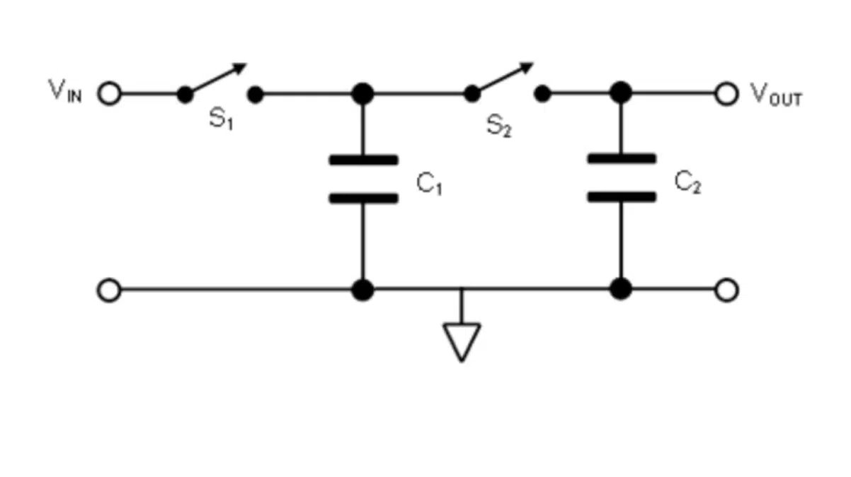
A switched-capacitor circuit is a discrete-time circuit that exploits the charge transfer in and out of a capacitor as controlled by switches. The switching activity is generally controlled by well-defined, non-overlapping clocks such that the charge transfer in and out is well defined and deterministic.

These circuits can be thought of as a type of sample and hold circuit, where values are sampled and passed around through the circuit to achieve the desired functionality. 

A switched capacitor circuit with non-overlapping clocks. Recreated image by authors used courtesy of Ma et al. 

Switched-capacitor circuits are very popular in applications such as filter designs thanks to their extremely accurate frequency response along with good linearity and dynamic range.

As we’ll see later, the discrete time-frequency responses of switched-cap filters are set entirely by the capacitance ratios and the circuit clock frequency, allowing the response to be set precisely on the order of 0.1%. Continuous-time filters, on the other hand, set their frequency response based on RC time constants, where values can vary by as much as 20% due to process variations.

Switched-capacitor Resistor 

The most fundamental building block of switched-capacitor circuit design is the switched-capacitor resistor. As mentioned, this circuit has two non-overlapping clocks of the same frequency, ø1 and ø2. To analyze this circuit, we’ll look at two stages. 
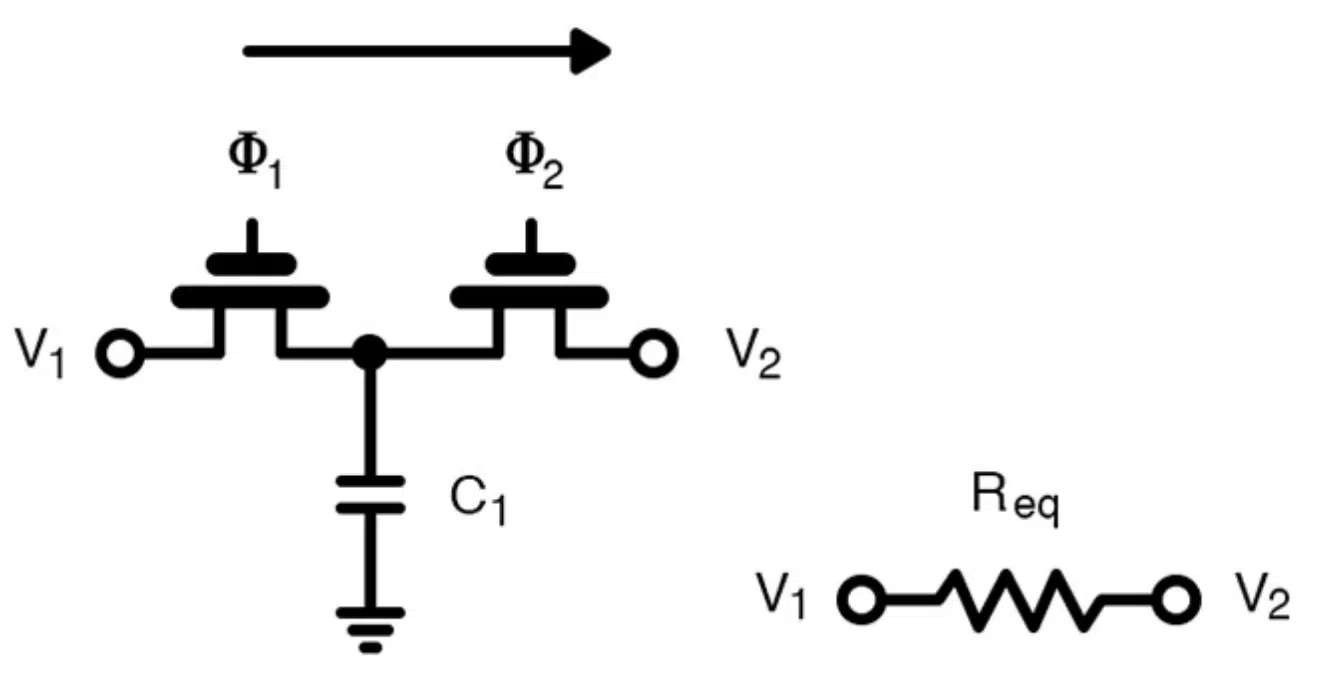
A switched-capacitor resistor. Recreated image by authors used courtesy of Carusone et al. 

In the first stage, switch 1 is turned on while switch 2 is turned off. In this setup, the charge flows from node V1 into the capacitor. In the second stage, switch 1 opens while switch 2 is closed. At this point, C1 is connected to node V2 and will either charge or discharge until the final voltage on the capacitor is at V2. The total value of this charge at each stage is given as

Q1=C1V1

Q2=C1V2

If we were to consider the total change in charge, we get the following equations:

ΔQ=C1(V1−V2)=C1ΔV

Knowing that current is defined as a change of charge with respect to time and that our change in time is nothing more than our clock period, we can get the average value of current across this switched capacitor:

Finally, we can use the above equation to find the equivalent resistance of the circuit: 
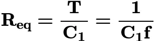
A quick note: I would be remiss not to mention that the previous analysis assumes that the charge transferred per clock cycle is constant over many cycles, allowing us to approximate average currents and resistances. For situations in which the input signal is changing quickly relative to the sampling frequency, a discrete-time z-domain analysis is required. 

Area Savings and Controlled Frequency Response

From these results, we can see the magic of switched-cap circuits: they allow designers to create very tightly controlled resistance that depends only on the clock frequency and capacitor value. 

One benefit of this technique is that it helps save space. Achieving large resistances generally requires a sizable amount of silicon area. Both factors can be made significantly smaller with switched-cap circuits. 
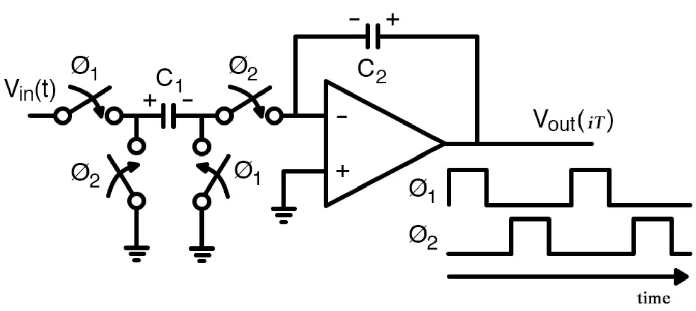
A switched-capacitor integrator with non-overlapping clocks. Recreated image by author used courtesy of Tenhunen et al. 

Another benefit is the fact that mismatch between resistors and capacitors in a continuous-time RC filter is limiting. Matching between similar devices tends to be much better (capacitor to capacitor) as opposed to different devices (capacitor to resistor), making switched-cap filters more precise with their frequency response. 

Finally, since our resistance value is set totally by the capacitance value and the frequency, we can dynamically change our filter’s frequency response by changing the clock frequency. 

The applications of switched-capacitor circuits are far and wide—and for good reason. Many circuits from filters to ADCs leverage these techniques for their area savings and tightly controlled frequency responses. 

Related

Source: All About Circuits

Recent Posts

KYOCERA AVX Releases Vibration-Proof SMD Aluminum Electrolytic Capacitors for Harsh Industrial Designs

26.8.2026
8

YAGEO Adds X8 Flexible-Termination Automotive MLCCs for 150°C Designs

25.8.2026
34

Current-Dependent Inductors: Using Non-Linear Inductance in Buck Converters and PFC Stages

24.8.2026
27

Passive Components for Industrial Automation and Robotics (Dossier Report 08/26)

20.8.2026
98

Advanced Electronics Markets Reshape Capacitor Demand for 2026/2027

20.8.2026
87

Panasonic Introduces Metallized Polypropylene Film Capacitors for Industrial and Automotive DC Applications

19.8.2026
63

Zowie Targets Embedded AI/HPC PDNs With Ultra-Thin Double-Sided MLPC Capacitors

19.8.2026
101

Modelithics CapV MVP Library: Measurement-Based Models for Varactor Chip Simulation

18.8.2026
30

Single Pair Ethernet for Humanoid Robot In-Robot Networks

17.8.2026
135

Upcoming Events

Sep 10
11:00 - 12:00 CEST

Equipment models and model strategies for Space Missions

Sep 29
16:00 - 17:00 CEST

Cybersecurity 2026

Nov 24
16:00 - 17:00 CET

Component selection with the WE REDEXPERT® DC-DC Converter Designer Tool

View Calendar

Popular Posts

  • Buck Converter Design and Calculation

    0 shares
    Share 0 Tweet 0
  • Boost Converter Design and Calculation

    0 shares
    Share 0 Tweet 0
  • LLC Resonant Converter Design and Calculation

    0 shares
    Share 0 Tweet 0
  • Earthing Systems and IEC Classification Explained

    0 shares
    Share 0 Tweet 0
  • MLCC and Ceramic Capacitors

    0 shares
    Share 0 Tweet 0
  • Flyback Converter Design and Calculation

    0 shares
    Share 0 Tweet 0
  • MLCCs in the Age of AI: Q2 2026 Market Tightness

    0 shares
    Share 0 Tweet 0
  • Capacitor Charging and Discharging

    0 shares
    Share 0 Tweet 0
  • Audio Capacitors: Choosing Capacitors for Crossover Circuits

    0 shares
    Share 0 Tweet 0
  • Ripple Current and its Effects on the Performance of Capacitors

    3 shares
    Share 3 Tweet 0

Newsletter Subscription


Passive Components Blog

© 2015–2026
All rights reserved

  • Home
  • Privacy Policy
  • EPCI Membership & Advertisement
  • About

No Result
View All Result
  • Home
  • Knowledge Blog
  • Dossiers
  • PCNS

© 2015–2026
All rights reserved