This article by Dr. V. Azbel, an Independent consultant on tantalum capacitors, discusses the wet test method limitations for evaluating of the stability and quality of tantalum capacitor anodes and tantalum powder.
Introduction
The wet test is a widely used method for incoming powder control. It assesses the acceptability of powders based on key electrical parameters of anodes, such as capacitance and leakage currents. This testing methodology involves manufacturing control anodes through an identical process by both the powder supplier and the customer. The only variable in this process is the powder itself.
For control purposes, a porous sintered pellet with a predefined porosity and neck size is produced from the powder. This pellet is then used to manufacture anodes with the required capacitance and leakage current characteristics.
However, the wet test has several limitations that can complicate the assessment of powder acceptability. Firstly, it has limited sensitivity, which can make it difficult to detect even small deviations in the powder’s properties. Secondly, the anode’s capacitance is primarily determined by the surface area of the pellet’s porous structure and the dielectric constant of amorphous Ta₂O₅. This means that capacitance is not influenced by factors that are critical to leakage currents, such as neck size, internal stresses, and defects. Thirdly, even when the powder parameters meet the specifications, they can be at the edge of acceptable values. Such deviations may be insignificant for capacitance but critical for leakage currents. Fourthly, the distribution of powder particle sizes, which affects porosity and neck size during sintering, is significant for maintaining stable leakage currents.
Problem Description
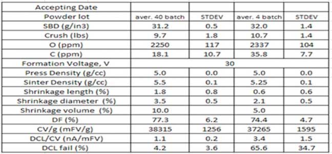
An issue was identified during operation: after 40 stable powder batches, the following four batches exhibited a sharp increase in failures caused by leakage current (DCL) spikes, despite the powders meeting specifications (see table).
Analysis:
The analysis revealed the following:
- Problematic batches exhibited lower shrinkage values, while the coefficient of variation (CV/g) values, which are related to the porosity of the sintered pellet, remained relatively unchanged.
- Despite this, the frequency of leakage current failures increased. Potential causes could include variations in the neck size, internal stresses, and defects in the porous structure of the sintered pellet.
To determine the key factor influencing the porous structure of the sintered pellet in the problematic batches, a mechanical testing method was employed. This method involved compressing sintered pellets while simultaneously recording a “stress-strain” curve.
Characteristics derived from the “stress-strain” curve enable the evaluation of changes in the porosity and defectiveness of the sintered pellet (see Appendix). By comparing the curve characteristics for pellets produced from acceptable and problematic batches, structural differences can be identified.
Analysis Results:
- The curve analysis revealed a significant reduction in yield strength (Ay) by more than 30% in problematic batches.
- There was a decrease in elastic modulus (E) by approximately 10–15%.
- The strain hardening coefficient (n) remained practically unchanged.
The decrease in Ay indicates a smaller neck size in the porous structure of problematic batches, which critically impacts leakage currents under identical formation voltage. The decrease in E aligns with a reduction in CV/g, while minor changes in n suggest a similar level of defectiveness.
Conclusions:
The analysis of mechanical and electrical tests suggests that the primary cause of problematic batches is likely related to changes in the particle size distribution curve of the powder, rather than internal stresses or defects in the sintered pellet. The particle size distribution curve is the final step in powder production and has a more direct and significant impact on neck size, which, in turn, affects anode characteristics during incoming inspection control.
This method demonstrated higher sensitivity compared to the wet test, enabling a clearer correlation between powder characteristics and final product quality to be established.
Recommendations:
Incorporate mechanical testing into the standard quality control procedures for powders.
APPENDIX
Strain-Stress curve parameters description for porous materials:
1. **Yield Strength (Ay):** The yield strength of a porous material depends on the size of its neck, which impacts the maximum permissible formation voltage. For porous materials, the yield stress can be calculated using the following equation: Ay = b*A0*(X/D)^2, where:
- b is an empirical constant
- Ay is the yield point of the sintered porous material
- A0 is the yield point of the deformed material
- X is the neck size (divided by the primary powder particle size, D)
- The ratio X/D cannot exceed 0.5
2. **Young’s Modulus (E):** Young’s modulus is related to porosity and affects capacitance. The behavior of Young’s modulus for a porous material can be described using the following equation: E = E0 (1-p/pc), where:
- E is the elastic modulus of a porous material with a porosity of p
- E0 is the modulus of a solid material at a density pc ~ 1
3. **CC Curve:** The CC curve can be used to calculate the strain hardening coefficient (n), which is related to the material’s defectiveness. This coefficient can influence leakage currents at the anode.
