Tantalum and Niobium capacitors are belonging to electrolytic capacitor types and they are known for its high capacitance in small dimensions (high energy and power density), reliability and stability of its parameters.
Traditionally, tantalums’ advantages over aluminum electrolytics capacitors have been found in terms of capacitance per volume, parameter stability over temperature, and longevity; tantalums in general do not suffer from dry-out problems or issues of dielectric degradation when stored discharged for long periods of time. However, tantalums are generally more costly, have a more limited range of available capacitance and voltage values.


The main types include:
- Tantalum solid electrolytic capacitors
- with MnO2 electrolyte
- with conductive polymer electrolyte
- Niobium and NbO solid electrolytic capacitors with MnO2 electrolyte
- Tantalum wet electrolytic capacitors
We will learn more about these types in the following chapters.
Construction and Manufacturing Process
Tantalum capacitors are manufactured from a powder of relatively pure elemental tantalum metal. Niobum capacitors from niobium metal powder and NbO capacitors from NbO powder with metal-like properties.


The following manufacturing process chart describes common tantalum chip MnO2 solid electrolyte manufacturing flow. The process is identical also for niobium and NbO chip capacitors.
The powder is compressed around a tantalum wire (known as the riser wire) to form a “pellet”. The riser wire ultimately becomes the anode connection to the capacitor. This pellet/wire combination is subsequently vacuum sintered at high temperature (typically 1200 to 1800 °C) which produces a mechanically strong pellet and drives off many impurities within the powder. During sintering, the powder takes on a sponge-like structure, with all the particles interconnected into a monolithic spatial lattice.
The dielectric is then formed over all the tantalum particle surfaces by the electrochemical process of anodization. To achieve this, the “pellet” is submerged into a very weak solution of acid and DC voltage is applied. The total dielectric thickness is determined by the final voltage applied during the forming process. Initially the power supply is kept in a constant current mode until the correct voltage (i.e. dielectric thickness) has been reached.
The next stage for solid tantalum capacitors is the application of the cathode plate (wet tantalum capacitors use a liquid electrolyte as a cathode in conjunction with their casing). This is achieved by pyrolysis of manganese nitrate into manganese dioxide in MnO2 parts (as shown on the chart) or polymerization in case of conductive polymer types.
Top of the anode is then covered by layers of graphite and silver paste for good conductivity and assembled into a leadframe. The leadframe function as a holding media for rest of the manufacturing process – moulding, testing and ageing. In final process the capacitors are cut, trim & formed and creates its final terminations.


Polymer and Manganese Dioxide MnO2 Solid Tantalum Capacitors
Introduction
Cross section schematics of typical SMD tantalum chip construction is shown in Figure 4. and 5.


Tantalum metal has a dielectric constant of approximately 27. The price for solid tantalums is relatively high due to mainly the high cost of the tantalum powder. The solid electrolyte theoretically has no limitations in operation and storage time. The capacitance range extends up to some thousands µF. The capacitors are characterized by a high CV product per volume unit, especially when high CV powders above 200k CV/g are introduced for low voltages and above 80k CV/g for higher voltages.
The conventional solid electrolyte is MnO2, however conductive polymer types are more and more favorite due to its lower ESR and reduced ignition features. On the other hand the MnO2 types are more robust against thermo-mechanical stress, stable electrical parameters under high temp & high humid environment, thus high reliability and longer operation life time applications still uses mostly established reliability MnO2 types as the main tantalum solid capacitor technology.
Physically, the capacitor also has a high density. Thus, lead mounted components always should be fixed mechanically against their substrate. This type requires large margins to the forming voltage that usually amounts to 2 to 4 times VR. For automotive and other high reliability applications ratios higher than 4 is required while for consumer electronics the ratio around 2 may be quite sufficient. The higher ratio favors not only higher reliability but also a better capacitance stability.
On the other hand higher VF/VR ratios means a correspondingly lower volumetric efficiency (capacitance is inversely proportional to the dielectric thickness). The maximum VR stops at 125 V DC for capacitors with polymer electrolyte and 100V DC for MnO2 types. However derating rules are different. It is recommended to derate MnO2 types by 50% for current surge circuits (directly on battery or DC/DC input) and 20% for non-high surge current applications (DC/DC output, timing, coupling/decoupling …). Tantalum polymer derating is recommended 10% for up to 16V capacitors and 20% for >16V capacitors for all kind of applications.
The capacitance stability is good (∆C/C ≤ ± 5%) and the tolerances range from (±5) ±10% to ±20%. The reverse voltage should, at a maximum 85 °C be limited to the least value of the alternatives: 10 % of VR or 1V. The continuous reverse voltage operation is not recommended, however small uneven spikes, such as diode overshoot voltage is acceptable. Chip designs are becoming very common and are well documented, with a functioning international standardization some basic case sizes have been established. However the market need and manufacturers feedback was faster then standardization and there are number of other case variants with different letter codes per manufacturing that may be very confusing in some cases – as the same letter from one manufacturer has different dimensions to the other.
As an example AVX X case is 1.5mm low profile variant of standard D case 7343 chip (AVX X case is equivalent to KEMET’s W case), however KEMET X case is a taller 4.3mm variant of standard D case 7343 part. (KEMET X case is equivalent to AVX E case).
The case size variants from manufacturers on market is in fact so wide that they are now using nearly complete alphabet options and began to use also numbers or combination of letters and numbers for different case size dimensions. The following table shows the common few sizes of a series that has acquired international acceptance under the same letter code:

SMD Chip Construction Variants
The most common construction design shown on Figure 5. is called J-lead type as per the termination shape. There are also some other construction designs on the market – see Figure 6. below.
- J-lead – most common, cost effective tantalum capacitor design with J-lead robust termination that works like a springs absorbing mechanical shocks and vibrations
- Undertab (facedown) – termination placed at the bottom of the case. This allows high density board mounting (no solder on capacitor sides) and also maximize its energy density / maximum capacitance and CV by inner space for larger anode. It does not allow solder quality visual inspection so this solution is not preferred by high rel applications.
- Diced design – such as TACmicrochip on figure below – proprietary AVX construction combining tantalum wafer and dice through technology allowing miniaturization down to 0201 case size. Diced designs are available also by other vendors such as Kemet/NEC or Vishay – most in combination with undertab configuration to maximize its CV.
- Conformal – original Spraque design – Vishay/Nichicon (AVX now) of dipped coated tantalum anodes. Advantage is in large, high CV anode, unmolded package is however not so flat with potential high speed pick and place issues.


Failure modes, Self-healing, Burn-in, Acceleration Factor (AF) and Derating
At first it has to be said that tantalum capacitors have been developed are representing one of the most reliable capacitor technology, historically linked with high rel applications. Nevertheless, solid tantalums sometimes are randomly stricken by short circuits. If the circuit has a high impedance it may happen that the failure disappears. A kind of self-healing has occurred. This is called sometimes a “scintillation”. Under certain conditions this kind of self-healing may occur also in circuits where the impedance is low. The reasons for this type of failure have been the subject of comprehensive researches and tests. After the forming the oxide film contains a number of weak sites caused by impurities in the tantalum metal or at sites of crystalline defects. If a voltage is applied gradually these sites will be the place for local higher currents that generated heat and heal the defect site. This is true for both MnO2 and conductive polymer while the mechanisms and effectiveness are different.
The local current generates a heat that creates temperatures in the micro spot of 400 to 500 °C. At that temperature the manganese dioxide in the case of MnO2 types is reduced to a lower degree of oxide (Mn2O3) with a several orders of magnitude higher resistivity. An insulating “patch” is formed over the leakage site, the local leakage current is choked and the capacitor self heals. This type of self-healing is provoked during the production phase by a voltage load, a so called voltage aging, that for every eliminated leakage site successively forces the leakage current down.


MnO2 self-healing considerations:
- microscopic localized mechanism with “no” influence to Capacitance, ESR
- “no” impact to DCL
- 100% hard surge current screening mandatory for ESA/MIL
- self healing and capacitor recovery may be limited in combination of following factors:
- high circuit resistance circuits >100kOhm
- aggressive reflow (=higher thermal damage to dielectric)
- very high derating >70%
MnO2 Tantalum Capacitors Design Considerations
While tantalum self-healing process is bringing high reliability for the MnO2 based tantalum capacitors, the ignition if-overloaded, pose an important point for a careful evaluation of its circuit applications. The following are general guidelines regarding the application of Ta-MnO2 capacitors:
- Use series resistance – if applicable: limiting the external current available to a fault greatly reduces the chance of a fault site reaching the critical ignition temperature. Historically a series resistance of 1 to 3 ohms per applied volt has been recommended, this is not any more required. Modern designs may not tolerate this much ESR, and larger devices may contain sufficient electrical energy when charged to self-ignite should a fault suddenly appear. In these cases, de-rating and device screening are particularly important.
- Derate voltage: Derating is the most effective way to increase steady-state reliability, derate to 50% of rated voltage, and as much as 70% when series resistance is extremely low, on the order of 0.01 ohm per applied volt or less. If currents are externally limited – in low/no surge applications, 20% derating may be sufficient.
- Burn-in carefully: Many tantalum failures occur on first power up of an assembled device, as a result of assembly-induced dielectric faults. Facilitating successful self-healing through gradual application of voltage via a current-limited source may avert some of these failures. Subsequent exposure to maximum expected electrical and environmental stresses will serve as a proof test, since Ta-MnO2 capacitors that survive a given set of stresses once are likely to survive them almost indefinitely.
- Limit transient current: Current flows in excess of the manufacturer’s stated surge current limit are to be avoided, including those arising from non-routine events, such as hot-plugging of batteries or power supplies, short-circuit faults of system outputs, etc. In absence of a surge current specification, a value Imax<Vrated/(1+ESR) has been suggested.
- Observe ripple current/temperature limits: Ripple current ratings are typically based on the amount of ripple required to produce a given rise in device temperature above ambient. Excepting cases where the resulting waveforms would violate voltage or surge current limits, ripple current limits are a thermal management issue. Evaluate the test conditions under which the datasheet ripple limit figures are specified, and adapt those limits according to actual application conditions.
Polymer Capacitors Self-healing and Derating
There is some self-healing effect also on tantalum polymer types as due to the high spot temperature the conductive polymer may evaporate / peel off (delaminate) or oxidize to high insulating state, thus the failure spot is eliminated. In effect, the capacitor reduce its high leakage through the defective site. In comparison, the self-healing on MnO2 is still considered as more effective, especially at lower current. On the other hand the self-healing in MnO2 parts is releasing some free oxygen that may extend the ignition failure mode. This is also one of the reason for higher derating (50%) of MnO2 types for high current circuit applications.
Polymer capacitors are much more robust against ignition and surge failures compare to MnO2 types. It is thus also reflected in its application derating recommendations usually as low as 10% up to 16V capacitors and 20% for >16V. See below applied voltage vs component rated voltage recommendation table:


polymer self-healing by evaporation


polymer self-healing by oxidization


ESR reduction
ESR can be reduced by change of MnO2 solid electrolyte to more conductive polymer material, however there are also other ways to reduce ESR by change of the construction and anode shape.
One way to reduce the ESR is to shorten the current path to the capacitor elements in the center of a pellet. Several methods to achieve this are shown in the following schematic of different designs. In Figure 9. design example No. 2 the rough surface of the coated anode is covered with the outer silver paint. Compared to the conventional anode in design No. 1 the average distance between the equipotential silver paint plain and the dielectric is reduced which means a reduced ESR.
A further ESR reduction is achieved by dividing the tantalum pellet in several elements that are connected in parallel – so called multi anode technology – where the current paths are reduced considerably and the conductive paint surface is even larger than in design No. 2. The method is introduced in recent years and will certainly be developed further. Roughly the ESR is inversely proportional to the number of elements in parallel.
Note: When improvement of “ESR” is mentioned we mean ESR value measured at standard measurement conditions = 100kHz “high frequency” important for SMPS output capacitor performance. The multiple anode or rough anode design is in fact using a “skin” effect that improves ESR at higher frequences while ESR at lower freq. such as 120Hz is not impacted or slightly higher as it is driven mostly by dielectric losses.


The ESR (skin effect) depends also on the layers coating the manganese dioxide electrolyte or conductive polymer. First the buffer between the electrolyte and the silver paint, i.e., the carbon layer, then the silver paint that is bonded to the leadframe by a silver adhesive. Layer thickness and distribution, material and treatment during production, all contribute to a low ESR that has to remain low even after environmental exposure.
Reverse Voltage
Solid tantalum electrolytics are considered as being able to stand more reverse voltage than wet electrolytics. The diode function is in other words not equally evident. The diode in the equivalent circuit ought to be supplemented with a Zener-diode. What, then, the Zener voltage is varies according to certain short time investigations from 15 to 40% of VR, depending on lot and manufacturer. Long term investigations point to more conservative values. This is underlined by the fact that advanced powder technology has increased the sensitivity to reverse voltages. Some leading manufacturers may have different recommendations for reverse voltage. If nothing is said about reverse voltage limitations, we should for high reliability applications choose the least of applicable values from following alternatives:
Temp. range & Derating
- -55/+25°C: 15% VR,
- +25→+55°C: 15%→ 10% VR,
- +55→+85°C: 10%→ 5% VR,
- +85→+125°C: 5%→ 1% VR,
OR
- of short duration maximum 1 V,
- continuous operations maximum 0.5 V
Solid Tantalum Capacitors Properties
Capacitance versus temperature

Capacitance versus frequency


The higher the porosity and the finer the powder and worse conductivity (MnO2) the sooner the capacitor starts loosing capacitance due to the increasing time constant of the farthest in localized capacitor elements in the pellet. On the contrary, when the ESR is reduced the time constants decrease. That means that the so called capacitance roll-off is moved toward higher frequencies and the capacitance decrease will be correspondingly smaller. The effect of multianode is demonstrated in the following figure on MnO2 part that shows examples from 470 µF / 6.3 V tantalums of different designs. The impact of multianode construction for polymer tantalum is not so big change in capacitance vs frequency characteristics (as it is already more-less flat), but to the absolute ESR value.

There is practically no ESR temperature dependence on polymer electrolyte and small dependence on manganese dioxide electrolyte – see Figure 14.
ESR versus temperature


ESR versus frequency


Tan δ DF versus frequency

Note the difference in frequency dependence of the two loss characteristics ESR and Tan δ in Figures 15. and 16. The influence of the linearly decreasing ESR in Figure 15. is visible at lower frequencies in Figure 16. but becomes more and more negligible when the frequency increases, just as the formula predicts: Tan δ = ESR x ωC.
DCL Leakage current versus ambient temperature
The MnO2 DCL specification limit for standard parts is usually given as:
DCL = 0.01 x CV
,where C=capacitance, V=rated voltage … thus 100μF 10V MnO2 capacitor has a DCL standard limit as 10μA at rated voltage. In practice, by rule of thumb, typical leakage current is about ten times lower, so in real measurement we can expect DCL to be around 1μA for the 100μF 10V part.
The basic DCL leakage current level on MnO2 capacitors is typically 10x lower compare to the polymer capacitors. Thus for polymer tantalum capacitors, DCL specification limits follow:
DCL = 0.1 x CV
the 100μF 10V polymer capacitor has a DCL standard limit as 100μA and typically we can measure around 10μA at room temperature.
Important note is that due to the continuous improvement leakage current limits may be specific to series and manufacturer. Low leakage series or consumer highest CV series (with higher DCL) are available on the market that differ with DCL specification limits to the above general equations. It is always a good idea to check the manufacturer specification datasheet.
Normalized DCL leakage current plot as shown in Fig 17. is valid for both MnO2 and polymer types, however the absolute DCL values differ !


Leakage current versus voltage
The Figure 18. above shows drop of the DCL with applied voltage (valid for both MnO2 and polymer types). By rule of thumb, DCL drop in one range with 50% derating. So taking an example of the 100μF 10V MnO2 capacitor with a DCL limit as 10μA at 10V rated voltage, we can assume the maximum leakage current values as 1μA at 5V applied and typical values would be around 0.1μA.
Leading manufacturers are providing now high fidelity simulation tools, where electrical characteristics of CAP, ESR, IMP, DF, DCL and S-parameters can be followed for individual capacitor part number.
Solid Niobium and Niobium Oxide Capacitors
Niobium is a sister metal to tantalum, and shares many chemical characteristics with it, in addition to a few disadvantages and advantages of its own when used as a capacitor dielectric.
Niobium capacitor technology has existed for decades, but its limitation in maximum rated voltage, lower volumetric efficiency, incompatibility with low ESR polymer electrode, limited range and number of vendors keeps this technology as a niche line of tantalum capacitor industry today. On the other hand, there are still some advantaged (such as lower cost, safety and reliability) that worth a closer look and consideration.
Brief History
Capacitor manufacturers have been evaluating niobium material for years every time the tantalum supply situation becomes unstable. Its lower cost base was also evaluated in order to replace low-voltage aluminium electrolytics.
Development of the first niobium capacitors started in former USSR already in 1960’s motivated by shortage of tantalum there. However, at that time, niobium powders were not available in appropriate low impurity, high quality level and the capacitor reliability was inferior to the tantalum capacitors.
Niobium-based material as easier to get and more abundant in nature captured attention by most of the leading tantalum manufacturers especially after the tantalum shortage and supply chain issues around year 2000. Beside niobium metal powder, NbO material has been introduced with metal conductivity level by J.Fife (U.S. Patent 6,391,275 B2) resulting in some advantage for capacitor application properties. Upon the new development and availability of low impurity Niobium/NbO powders within years 2001-2003 companies AVX, EPCOS (tantalum division acquired by KEMET in 2007), Hitachi (bought by Holy Stone in 2009, acquired by Vishay in 2014), KEMET, NEC and Vishay announced some early sampling and preproduction of niobium-based capacitors in 2002.


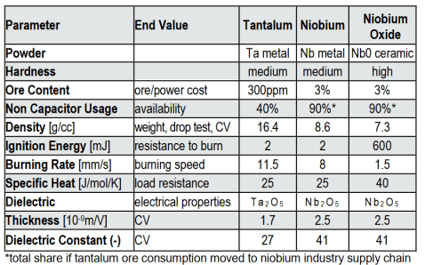
Construction of SMD chip niobium capacitors is identical to tantalum including manufacturing process route. Niobium or Niobium oxide powder are used instead of tantalum and the dielectric is Nb2O5 instead of Ta2O5 see Fig. below. Dielectric constant of Nb2O5 is 41 ~ twice higher compare to tantalum pentoxide, hower its density and electrical breakdown strength is about a half. This does not bring CV advantage of Nb/NbO capacitors over tantalum, however as the dielectric has to be ~ twice thicker compare to tantalum it brings benefits to stability and reliability.


Nevertheless, despite the very optimistic first results, niobium posed some early technical challenges that capacitor makers were struggling to overcome. The obstacles included high dc-leakage current (two to five times worse than for tantalum capacitors), increase of DCL with lifetime and susceptibility to damage by thermal shock during reflow manufacturing process. Low-CV capabilities have also been a problem because of the lack of high grade, high purity capacitor-grade powders at that time.
Tantalum supply chain has consolidated in further years and the urgency for niobium-based capacitor development dropped versus requirements for lower ESR tantalum capacitors with conductive polymer electrodes. In co-incidence, conductive polymer junction to Nb2O5 dielectric is resulting in even higher DCL that practically disqualify its use with niobium-based capacitors. This next technical challenge would require additional development resources to address some basic physics issues related to potential development of polymer niobium-based capacitors. Hence, most of the manufacturers terminated its further development effort, focusing its development power to the other priorities and obsoleted their niobium-based capacitor lines.
Niobium-based capacitors with MnO2 solid electrolyte are still on the market with high reliability versus cost unique value in certain applications. Vishay obsoleted its SMD chip niobium capacitors in 2017 and the major supplier of SMD NbO capacitors today is AVX Corporation that dedicate its product to mainly automotive, aircraft, defence and high safety applications. Axial niobium capacitors are also still made in Russia by company OJSC ELECOND for industrial, defence and high reliable applications.
Niobium-based Capacitor Technology and Features Background
Volumetric efficiency
Niobium, as mentioned, is in many ways behaving very similar to tantalum capacitors. Niobium or NbO material can be processed into a form of powder with a stable oxide Nb2O5 (vs Ta2O5 in case of tantalum) as a high dielectric constant insulation. Niobium pentoxide has a dielectric constant about twice as high as that of tantalum oxide, however the density of niobium is only half that of tantalum, resulting in similar or slightly lower volumetric efficiency compare to tantalum capacitors.


Abundance
an important advantage of niobium is the abundance of niobium ore in nature relative to tantalum ore; this relative abundance equates to lower cost and better availability within the capacitor marketplace.
Flame Retardancy
Niobium metal is behaving like tantalum capacitors. However, as one of key advantages niobium oxide has a far higher ignition energy than tantalum which results in a significant reduction (up to 95%) of the ignition failure mode of niobium oxide capacitors when compared to conventional tantalum devices.
Sub-oxides stability
One of the “small” differences between niobium and tantalum that makes a big impact to capacitor features is that niobium sub-oxides are stable unlike on tantalum. There are no long term stable suboxides between tantalum and the dielectric tantalum pentoxide (Ta2O5). There are at least two suboxides on niobium-based materials that are stable: NbO and NbO2.
NbO is a material with metallic type of conductivity that can be processed and used as the main anode material same way as Nb or Ta metals (used by NbO capacitors as anode material)
NbO2 is an oxide with semiconductive behaviour that exists together with the “main” dielectric Nb2O5 on the junction with Nb/NbO anode. The NbO2 oxide may grow with temperature (such as during the hot spot in dielectric failure site) and its responsible for the unique “self-arresting” mechanism.
Self-arresting mechanism:
In addition to the self-healing known on conventional tantalum MnO2 capacitors, the NbO capacitors are featuring one more feature when it is exposed to local breakdown, the NbO2 layer on dielectric will grow as a “second” insulation protecting the part to go to short circuit mode. Such part then continues in normal operation even in occasion of the main Nb2O5 dielectric breakdown. Under a specified operating conditions, NbO capacitors are thus one of the safest capacitor technologies on the market.


Operating temperature:
Another difference to tantalum capacitors is that Nb2O5 dielectric is more sensitive to higher temperature operation above 85°C. Reliability up to 85°C may be considered as better, about equal at 105°C and inferior at 125°C requiring higher derating compare to tantalum capacitors.
The natural high reliability performance of niobium-based capacitors up to 85°C (including safety margin) makes them suitable for high performance industrial, automotive, defence, medical support, aerospace applications even at safety critical applications.
Rated voltage:
As mentioned, the density of niobium is only half that of tantalum, so twice as much material is needed per unit volume to provide the same charge. The Nb2O5 dielectric constant is higher, but you must form a thicker niobium oxide dielectric for the same voltage. That is good to reduce further the electrical field stress to the dielectric (and achieve better reliability) on one side, but there is a certain limitation in maximum dielectric thickness / maximum rated voltage, driven by powder impurities and formation techniques on the other site. In result, niobium-based capacitors are featuring significantly lower maximum rated voltage compare to tantalum capacitors.
Limitations
One limitation of niobium-based technologies, is a lower maximum rated voltage (~10-16V) and lower CV in comparison to conventional tantalum capacitors with MnO2 (still higher compare to other capacitor technologies).
As tantalum supply chain consolidated, niobium-based technology has been ceased by number of manufacturers, thus limited sources and product range are the main current issues of the technology apart of the technical borders discussed above. Case sizes, mounting guidelines etc of the niobium-based chip capacitors are however identical to tantalum and tantalum polymer capacitors, that can be considered as drop-in alternative on the same footprint to avoid single source issues. Thus, the niobium-based capacitors can be considered as additional option where tantalum capacitor designs are considered with enhanced safety feature.
Properties
In comparison with solid tantalums the temperature dependence is slightly higher.
Capacitance versus temperature


temperature in solid niobium electrolytic capacitors.
Capacitance versus frequency


frequency in solid tantalum and solid niobium/niobium
oxide electrolytic capacitors of the same voltage and capacitance ratings
The higher the porosity and the finer the powder, the sooner the capacitor starts loosing capacitance due to the increasing time constant of the farthest in localized capacitor elements in the pellet. Because niobium powders have a slightly higher porosity than tantalum its frequency dependence is correspondingly higher as seen on Figure 23. above.
ESR versus temperature
Because ESR is dominated by the MnO2 counter electrode we may expect approximately the same behavior as in solid tantalum capacitors.
The ESR in niobium / NbO electrolytic capacitors is slightly higher than that of solid tantalums at frequencies around 100 Hz. The difference decreases successively and is at 1 to 10 MHz negligible.
ESR versus frequency


tantalum and niobium/niobium oxide electrolytic capacitors based on
100 uF/6.3 V components
Leakage current versus ambient temperature


temperature. Reference: DCL at 25 °C
Applications
Where the niobium capacitors bring its benefits:
- High reliability, long term operation, safety circuits, with a “standard ESR requirements” up to 8V application voltage operating in environment up to 85°C safety (105°C qualification) with a little more space on board needed compare to tantalum capacitors (still smaller then aluminium electrolytics). The parts showing high mechanical robustness against shocks and vibrations and stable electrical performance (over MLCC class II capacitors).
There is a wide range of applications were niobium-based capacitors can bring its benefits in low cost for high safety and reliability standards.
applications with benefits from downsizing of aluminium electrolytics capacitor:
- Consumer such as home theatres, game controllers, white goods controllers.
high value in lower cost versus safety and reliability
- Industrial with enhanced safety feature such as smoke detector, security electronics etc
- Automotive such as cabin electronics and telematics
- Aircraft – on board entertainment, telematics, defence (COTS+ version available)
Summary
Niobium-based capacitors present a niche capacitor market share within the tantalum capacitor industry. Nevertheless, some of its unique features, especially high safety, no short circuit failure mode under standard operating conditions and high reliability bring its value to the end users to remain as a viable capacitor solution in longer term future.
The NbO capacitor within its rated voltage is not likely to fail as a short circuit in applications that makes it one of the safest capacitor technologies on the market at the class of up to 8V operation voltage – counting with 20% derating of its maximum 10V range. The main applications are then 3.3 and 5V lines where safety is the prime focus such as aircraft or automotive electronic hardware.


Wet Electrolytic Tantalum Capacitors
Introduction
Wet tantalum capacitors have several advantages over solid tantalum, aluminum electrolytic, and ceramic capacitors. As with all other capacitors, these advantages lead to a very specific “sweet spot” or focused area of applications where the wet tantalum capacitor is the best and preferred choice. Wet tantalums require little derating and offer higher voltages (75 V, 100 V, and 125 V) than solid tantalums.
Rating for rating, wet tantalum capacitors tend to have as much as three times better capacitance / volume efficiency than aluminum electrolytic capacitors. Wet tantalums, with their hermetic case designs, have very long life and low DC leakage. Fig. 26. below shows where the wet tantalums falls within the capacitor families. As shown, they offer higher capacitance and voltage than solid tantalums, but smaller size than aluminum devices with the same rating.


As we already have indicated there are two most common designs of a wet tantalum electrolytic with different cathode design: the sintered case and the proprietary cathode design style. In history there were one more style – foil tantalum wet capacitor that existed either with a plain or an etched anode foil. Because this design was expensive, relatively unusual and normally can be replaced with a wet aluminum electrolytic we will just mention its existence.
A typical construction of a sintered designs with a tantalum case MIL-C-39006 (left) and proprietary cathode DLA 93026 (rigth) may look like the one in Figure 27.


The wet sintered tantalum electrolytic with proprietary cathode system has the highest CV product per volume unit of all polarized electrolytics. In the first hand it depends on the formation voltage that, compared to solid tantalums, is approximately three times lower. This means that the corresponding dielectric thickness of a certain rated voltage will be only one third of that for the solid one and the capacitance three times greater. Thus, the solid tantalum capacitor needs a surface three times larger than that of the wet one for getting the same capacitance.
The wet sintered tantalum capacitor also has the lowest leakage current of the electrolytics. It is comparable with that of paper capacitors.
Exactly as with solid tantalums the density is so high that lead mounted types should be attached mechanically against its substrate.
The electrolyte consists of concentrated sulfuric acid. Therefore, the weld between the connecting nickel lead and the tantalum lead from the sintered core is placed outside the can. The lead must not be bent inside the weld. Otherwise the risk is high that the seal is dam-aged and sulfuric acid leaks out.


The sulfuric acid has a freezing point of approximately –64 °C. Its liquid state may sometimes give the capacitance a certain position dependency. This dependency is often avoided by giving the sulfuric acid a gelatinous consistence. The gelled electrolyte also is favorable with respect to the leakage risk.
The sintered wet electrolytic still is manufactured in a variant with silver can. The risk, however, of silver dendrite formation that causes a short-circuit is relatively high and tantalum case is the preferred designs. The conventional tantalum cathode sleeve design as per MIL-C-39006 style (Fig 27. left) is limited by CV but it can stand a reverse voltage of 3 V up to 85 °C. The proprietary cathode design type as per DLA 93026 is offering significantly higher capacitance range and energy density but no reverse voltage is allowed.
The following series of diagrams are applicable to both Ag and Ta case styles if nothing else is said.
Properties
As other wet electrolytic capacitors also the wet tantalum has a strong temperature dependence of capacitance. It depends on the rather high resistivity of the electrolyte, especially at lower temperatures. This resistivity is, compared to solid electrolytes, high also at room temperatures which in turn is reflected on the presented frequency dependence measured at normal conditions. Figures 30. and 31.
Capacitance versus temperature


Capacitance versus frequency


The temperature dependence of silver-cased wet tantalum capacitors have a slightly broader curve range for low rated voltage and high capacitance values.
Note in Figures 30. and 31. that “high rated voltage – low capacitance” constitutes one of the limits of the curve range and “low rated voltage – high capacitance” the other limit.
The fine powder technology is a condition for the low voltage – high capacitance styles. The high porosity of the pellet, however, increases the ESR of the electrolyte due to the electrolyte filled ducts that are becoming longer and finer and more resistive. The capacitance elements farthest in the pellet consequently require longer time constants for charging. When the frequency increases these elements become ineffective, i.e., the capacitance decreases with frequency (Figure 31.).
The curve range in Figure 31. demonstrates a greater temperature dependence at low temperatures where the viscosity and resistivity of the electrolyte increase, more the higher the pellet porosity is. Consequently, at lower temperatures the upper limit of the curve range belongs to high capacitance designs.
ESR in silver-cased tantalums differs slightly from tantalum-cased wet capacitors by having a broader curve range at higher temperatures.
ESR versus temperature


ESR versus frequency


The frequency dependence of ESR is presented in a normalized form, i.e., as a ratio between the ESR at different frequencies and at 120 Hz. Compared to solid MnO2 tantalums the frequency dependence of the ESR in wet tantalum capacitors is smaller and tends to level out at higher frequencies.
DCL versus temperature


DCL versus applied voltage


The peculiar break in the leakage current curve de-pends on the derating that takes effect at 85 °C and stop further increase of the leakage current in spite of in-creasing temperature.
Reference: DCL at 100%VR.
The leakage current follows an almost linear dependence of the applied voltage – which should be the case if the dielectric acted as a pure resistor. The dielectric, however, is no pure resistor but a complicated oxide formation that together with the electrolyte and the base metal creates a valve function. Therefore the curve bends slightly downwards at lower voltages. If we compare with solid tantalums this characteristic is even more pronounced which has to do with the much larger margins to the formation voltage.
Failure modes
The most common failure mode is leakage of electrolyte through damaged glass-to-metal seals. The failure can be provoked by careless lead bending and, not the least, by temperature changes. It’s advisable to make sure that the manufacturer’s products can stand temperature changes.
Other wet electrolyte case sizes and styles
Surface-Mount


As the whole electronic component industry moved towards surface-mount technology, the wet tantalum capacitor had remained as an axial leaded device. The first early attempt to offer a surface-mountable wet tantalum capacitor was the Arcotronics SMTH. This was achieved by attaching special preformed SMD mounting tabs or terminations to the existing or standard axial tantalum case design. They could be manually soldered to the PCB using the tabs (see Figure 36.).
The next generation of surface-mountable wet tantalums was the M35 series, developed by Vishay. The M35 features a molded style with terminations. The design incorporates a complete T1 axial all-tantalum wet tantalum capacitor, which is welded to a lead frame, then molded (see Figure 37.).


The latest addition by Vishay is the T22 series that is the first “true” SMD wet tantalum capacitor. It has a hermetically sealed rectangular tantalum case with terminations and is available in either bulk or a reel pack option (see Figure 38. below).


High Energy


For high energy or bulk power applications, several axial wet tantalum capacitors are often connected in parallel and / or series. While customers can do this on their printed circuit board (PCB), the capacitor manufacturer can also provide a pre-assembled module or array of capacitors. The original arrays were made of the silver case capacitors, and there was actually a full MIL-PRF-3965 specification.
While these arrays are still available today, custom assemblies made from tantalum case wet tantalum capacitors available by more vendors such as Vishay, AVX, Exxelia. Example is a module that consists of wet tantalum case T1 capacitors on Figure 39.
wide variety of case materials and configurations to meet customer-specified performance requirements and are available with many termination options. Capacitor assemblies made include balancing resistors, diodes, and other components as needed to meet customer needs.


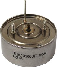
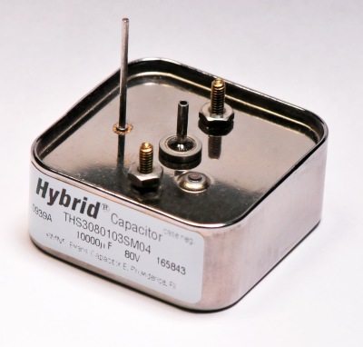
In some high energy or bulk power applications, the best solution may be the relatively new high energy, sometimes termed “hybrid,” wet tantalum capacitors. These capacitors utilize a tantalum anode and tantalum case, but need a hybrid cathode made by depositing a material such as ruthenium or palladium on a small piece of tantalum foil. These large case size wet tantalums reach capacitance values of over 72,000μF at 25V and are used in energy hold-up and pulse power applications.
Very specialized designs, made with titanium cases, a special electrolyte, and rated for high voltages, have been used in medical implantable ICD applications for over 20 years. An individual ICD capacitor may provide 400μF at 250V in the relatively stable environment of the human body at an ambient temperature of 37ºC. See Figure 40.
Military versions of the high energy “hybrid” capacitors were developed in various configurations with one or multiple anodes in a cylindrical/rounded square cases with radial terminations, such as illustrated on examples in Figure 41-43. below.