





Passive Components Blog
No Result
View All Result
  • Home
  • News
    • All
    • Aerospace & Defence
    • Antenna
    • Applications
    • Automotive
    • Capacitors
    • Circuit Protection Devices
    • electro-mechanical news
    • Filters
    • Fuses
    • Inductors
    • Industrial
    • Integrated Passives
    • inter-connect news
    • Market & Supply Chain
    • Market Insights
    • Medical
    • Modelling and Simulation
    • New Materials & Supply
    • New Technologies
    • Non-linear Passives
    • Optoelectronics and Isolation
    • Oscillators
    • Passive Sensors News
    • Resistors
    • RF & Microwave
    • Telecommunication
    • Weekly Digest
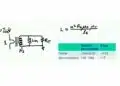
    Würth Elektronik WE-LHMI and WE-HCI power inductor comparison slide showing current ratings and maximum operating temperatures

    Power Inductor Selection: Ferrite vs Powder Core Trade-Offs, Würth Elektronik Webinar

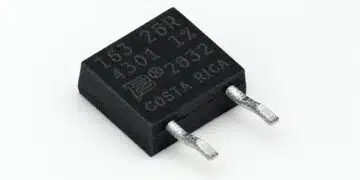
    Bourns PWR163 DPAK-style surface-mount power resistor with moulded housing, metal backplate and terminals

    Bourns Releases Power Resistor Adds Reverse-Pin Configuration

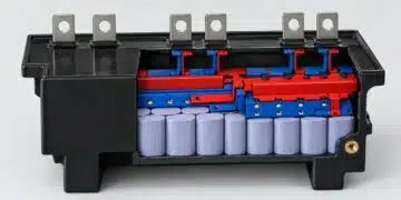
    Conceptual polypropylene DC-link film capacitor module with parallel cells and copper interconnections

    DC-Link Film Capacitor Modules: Inductance and Thermal Design, Jianghai-Europe Tech Memo

    Panasonic EVP-BX surface-mount tactile switches with top-push actuators and two-terminal construction

    Panasonic EVP-BX Quiet Tactile Switches for HMI Designs

    Motor Run Capacitor Safety Classes S0–S3: A Design Guide

    YAGEO Piezoelectric Sensors for Predictive Maintenance

    Wk 44 Electronics Supply Chain Digest

    TDK HVC28 and HVC29 high-voltage DC contactors with black housings and main power terminals

    TDK Introduces Gas-Filled High-Voltage DC Contactors up to 600 A

    Murata SWL RF coaxial switch connector measurement diagram and SWL-to-SWJ board-area comparison.

    Murata RF Switch Connectors Cut PCB Test-Point Area

    Trending Tags

    • Ripple Current
    • RF
    • Leakage Current
    • Tantalum vs Ceramic
    • Snubber
    • Low ESR
    • Feedthrough
    • Derating
    • Dielectric Constant
    • New Products
    • Market Reports
  • Knowledge Blog
  • Dossiers
    • Aerospace and Defense Passive Components Dossier
    • AI Hardware Dossier
    • Automotive Dossier
    • Industrial Robotics Dossier
    • Power Converter Dossier
    • Capacitor Dossier
    • Circuit Protection Dossier
    • Inductor Dossier
    • Resistor Dossier
    • Silicon Capacitors and Integrated Passives Dossier
  • Suppliers
    • Who is Who
  • PCNS
    • PCNS 2025
    • PCNS 2023
    • PCNS 2021
    • PCNS 2019
    • PCNS 2017
  • Events
  • Home
  • News
    • All
    • Aerospace & Defence
    • Antenna
    • Applications
    • Automotive
    • Capacitors
    • Circuit Protection Devices
    • electro-mechanical news
    • Filters
    • Fuses
    • Inductors
    • Industrial
    • Integrated Passives
    • inter-connect news
    • Market & Supply Chain
    • Market Insights
    • Medical
    • Modelling and Simulation
    • New Materials & Supply
    • New Technologies
    • Non-linear Passives
    • Optoelectronics and Isolation
    • Oscillators
    • Passive Sensors News
    • Resistors
    • RF & Microwave
    • Telecommunication
    • Weekly Digest
    Würth Elektronik WE-LHMI and WE-HCI power inductor comparison slide showing current ratings and maximum operating temperatures

    Power Inductor Selection: Ferrite vs Powder Core Trade-Offs, Würth Elektronik Webinar

    Bourns PWR163 DPAK-style surface-mount power resistor with moulded housing, metal backplate and terminals

    Bourns Releases Power Resistor Adds Reverse-Pin Configuration

    Conceptual polypropylene DC-link film capacitor module with parallel cells and copper interconnections

    DC-Link Film Capacitor Modules: Inductance and Thermal Design, Jianghai-Europe Tech Memo

    Panasonic EVP-BX surface-mount tactile switches with top-push actuators and two-terminal construction

    Panasonic EVP-BX Quiet Tactile Switches for HMI Designs

    Motor Run Capacitor Safety Classes S0–S3: A Design Guide

    YAGEO Piezoelectric Sensors for Predictive Maintenance

    Wk 44 Electronics Supply Chain Digest

    TDK HVC28 and HVC29 high-voltage DC contactors with black housings and main power terminals

    TDK Introduces Gas-Filled High-Voltage DC Contactors up to 600 A

    Murata SWL RF coaxial switch connector measurement diagram and SWL-to-SWJ board-area comparison.

    Murata RF Switch Connectors Cut PCB Test-Point Area

    Trending Tags

    • Ripple Current
    • RF
    • Leakage Current
    • Tantalum vs Ceramic
    • Snubber
    • Low ESR
    • Feedthrough
    • Derating
    • Dielectric Constant
    • New Products
    • Market Reports
  • Knowledge Blog
  • Dossiers
    • Aerospace and Defense Passive Components Dossier
    • AI Hardware Dossier
    • Automotive Dossier
    • Industrial Robotics Dossier
    • Power Converter Dossier
    • Capacitor Dossier
    • Circuit Protection Dossier
    • Inductor Dossier
    • Resistor Dossier
    • Silicon Capacitors and Integrated Passives Dossier
  • Suppliers
    • Who is Who
  • PCNS
    • PCNS 2025
    • PCNS 2023
    • PCNS 2021
    • PCNS 2019
    • PCNS 2017
  • Events
No Result
View All Result
Passive Components Blog
No Result
View All Result

Calculating for KVA in Single and Three Phase Transformers

4.4.2018
Reading Time: 2 mins read
A A

Source: Sensors online article

by Andrew Holland |Apr 3, 2018 1:37pm. Need to size a single or three-phase transformer? Transformer sizes are dictated by their respective KVA rating. Using common variables, one can compute for the required KVA rating or transformer size for a particular project, system or operation. This article provides basic formulas for finding the correct size of single and three-phase transformers using load voltage and load current.

RelatedPosts

Power Inductor Selection: Ferrite vs Powder Core Trade-Offs, Würth Elektronik Webinar

Bourns Releases Power Resistor Adds Reverse-Pin Configuration

DC-Link Film Capacitor Modules: Inductance and Thermal Design, Jianghai-Europe Tech Memo

Single Phase KVA Calculation

The formula for finding the required KVA or transformer size for single-phase power is the following:

Volts x Amps / 1,000 = KVA

Based on the equation, one would need to plug in the proper load/output (secondary) voltage and current (amps) to compute for KVA. Note that load voltage is not the same as line voltage, which is also known as primary voltage or input.

Example: Find the KVA or transformer size for load voltage of 120V 1PH and a load current of 50A.

120 x 50 / 1,000 = KVA

6,000 / 1,000 = KVA

= 6 KVA


Three-phase KVA Calculation

Businesses that require three-phase power need to add an extra component in the formula to arrive at the correct transformer size, i.e., square root of 3 (√3) or 1.732. This figure is a constant found in three phase, as the phases do not generate the same amount of power (simultaneously). Furthermore, three-phase transformers handle three lines of AC power, with each of the three lines 120 degrees out of phase from the other two lines.

With this in mind, the new formula can be found below:

Volts x Amps x √3 / 1,000 = KVA

Example: Find the KVA or transformer size for load voltage of 240 3PH and a load current of 60 amps.

240 x 60 x 1.732 / 1,000 = KVA

= 24.94 KVA (or 25 KVA after rounding up)


Future Expansion and Standard Transformer Sizes

Computing for the required KVA is not the final step in determining the proper transformer size. Most computations (especially for three-phase loads) do not provide a whole number. As a result, the value must be rounded up, as seen in the sample above. It is best practice to always round up and not down.

Next, in order to factor in future expansion and prevent risks associated with accidental overloading, one should add 20 percent of spare capacity. Taking the three-phase sample again, we simply add 20 percent to the rounded figure:

25 KVA + 5 = 30 KVA

Lastly, one may find that the specific transformer size needed is not being offered or is unavailable by the store or preferred manufacturer. In most cases, this is because there are standard KVA sizes for transformers. If you cannot find the size you need, simply round up again to the next standard KVA size.

For referencing, the standard KVA sizes for singe-phase transformers are 1, 1.5, 2, 3, 5, 7.5, 10, 15, 25, 37.5, 50, 75, 100, 167, 200, 250 and 333 KVA

Taking our answer from the single-phase example above – 6 KVA or 7.2 KVA (with 20% spare capacity); we can see that there is no standard single-phase equivalent available. As a solution, simply round up to the next standard single-phase KVA size: 7.5 KVA.

Standard sizes for three-phase transformers are 3, 6, 9, 15, 30, 45, 75, 112.5, 150, 225, 300, 500, 750 and 1,000 KVA

Taking our final three-phase figure of 30 KVA, we can see that it matches with a standard three-phase transformer size above, i.e., 30 KVA. No further rounding or conversion is needed, since 30 KVA is a standard three-phase transformer size.

Related

Recent Posts

Würth Elektronik WE-LHMI and WE-HCI power inductor comparison slide showing current ratings and maximum operating temperatures

Power Inductor Selection: Ferrite vs Powder Core Trade-Offs, Würth Elektronik Webinar

3.11.2026
9
MLCC construction image

Samsung Electro-Mechanics Patent Targets to Reduce Moisture and Cracks in High-Capacity MLCCs

26.10.2026
70
Silicon capacitors and integrated passives dossier cover

Silicon Capacitors and Integrated Passives Dossier Report 10/26

8.10.2026
80
TLVR multiphase coupled inductors, auxiliary ballast inductor

TLVR Coupled Inductors: Fast Load-Step Response and Current-Dependent Ballast-Inductor Optimisation

24.9.2026
121
Frenetic planar ER transformer simulation for a 5 kW 800 V-to-50 V PSFB converter, showing low-profile core geometry and high-current planar winding arrangement

5 kW 800 V-to-50 V PSFB Transformer Design for Data Centers

18.9.2026
129

Current-Dependent Inductors: Using Non-Linear Inductance in Buck Converters and PFC Stages

24.8.2026
93

Current Sense Transformers: Ferrite vs Nanocrystalline Cores for Accurate Current Measurement

5.8.2026
211

Ferrite versus Nanocrystalline Power Inductor Cores: Turns, Gap and Size

9.7.2026
286

From DCL to SSC: Bridging Electrical Symptoms and Structural Indicators in Tantalum Capacitors

7.7.2026
156

Upcoming Events

Nov 24
16:00 - 17:00 CET

Select the Correct Components for Your DC/DC Converter

Dec 1
16:00 - 17:00 CET

Developing low-noise mixed-signal systems

Dec 8
16:00 - 17:00 CET

WE-CCMF: Design Principles, Layout Guidelines and Measurement Results for High-Speed EMI Filtering

View Calendar

Popular Posts

  • Buck Converter Design and Calculation

    0 shares
    Share 0 Tweet 0
  • Boost Converter Design and Calculation

    0 shares
    Share 0 Tweet 0
  • September 2026 Interconnect, Passives and Electromechanical Components Market Insights

    0 shares
    Share 0 Tweet 0
  • LLC Resonant Converter Design and Calculation

    0 shares
    Share 0 Tweet 0
  • Capacitor Charging and Discharging

    0 shares
    Share 0 Tweet 0
  • Flyback Converter Design and Calculation

    0 shares
    Share 0 Tweet 0
  • RF Connector Types: How To Choose the Right One

    0 shares
    Share 0 Tweet 0
  • Passive Low Pass Filters: Fundamentals and EMI Design

    0 shares
    Share 0 Tweet 0
  • MLCC and Ceramic Capacitors

    0 shares
    Share 0 Tweet 0
  • Audio Capacitors: Choosing Capacitors for Crossover Circuits

    0 shares
    Share 0 Tweet 0

Newsletter Subscription


Passive Components Blog

© 2015–2026
All rights reserved

  • Home
  • Privacy Policy
  • EPCI Membership & Advertisement
  • About

No Result
View All Result
  • Home
  • Knowledge Blog
  • Dossiers
  • PCNS

© 2015–2026
All rights reserved