
The blog article written by Rick Liu, KYOCERA-AVX Corporation elaborates on DC blocking capacitor selection for mobile and wearable stereo high-fidelity audio.
Application Background
The representation of audio signals in analog and digital electronics can take many forms. Still, they must ultimately be converted back to their mechanical origins as the motion of air molecules propagating as waves. These waves are generated by moving a mass, often the cone of a speaker, back and forth around a neutral position. As such, any fixed offset in the audio signal, represented by a DC bias, is simply a waste of energy and possibly a source of imbalance in the resulting sound wave.
Series blocking capacitors are generally used for each audio channel to eliminate the potential of any DC component. While most capacitors will adequately remove the DC component from the output, each of the many varieties will also alter the actual audio signal to varying degrees. For high-fidelity applications, proper selection of these blocking capacitors can be a critical performance factor.
DC Blocking Capacitor Selection
For mobile and wearable applications, volumetric and height restrictions limit the available choices for capacitors with high capacitance-voltage (CV) characteristics. Multilayer ceramics (MLCC) cannot be used because of piezo noise and capacitance reduction at high voltage.
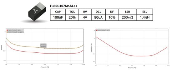
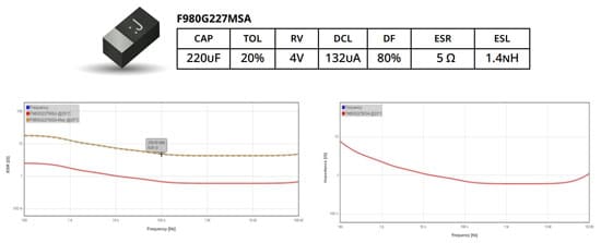
The only feasible devices to fit within an 0805 package and provide 100uF of capacitance at a minimum are of the Tantalum capacitors MnO2 and Tantalum polymer varieties. Two candidate capacitors from KYOCERA AVX were selected and are compared in the following tables.
The Tantalum MnO2 (F98 series – Fig.2.) offers high CV, while the Tantalum polymer (F38 series – Fig.1.) offers comparable CV along with extremely low series resistance (ESR).
Frequency Response
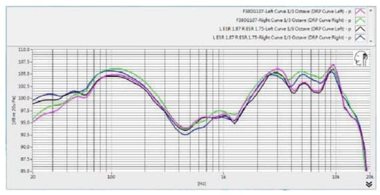
The frequency response of the F380G107MSALZT and F980G227MSA for left and right channels were tested, as shown in Figure 3. Two characteristics are worth noting in this data: the F38 exhibits greater attenuation than the F98 below 100Hz, and the difference between the left and right channel is worse for the F38 even beyond 1kHz.
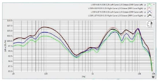
Given the superior frequency performance of the F98 series capacitors, the effect of ESR on the left and right channels can then be analyzed. The worst- and best-case combinations are shown in Figure 4, with the worst (4.5 dB drop) ESR of 4.83Ω and 0.25Ω shown in green and red, and the best (2.5 dB drop) ESR of 1.87Ω and 0.35Ω shown in blue and black. From 50 Hz to approximately 4 kHz, the difference between right and left channels was maintained within 3 dB.
F98 High CV Tantalum Capacitor for Maximized Capacitance in 0805 Case
Dynamic Range and ESR
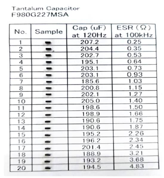
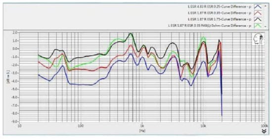
Measuring twenty F98 capacitors yielded a range of results for capacitance and ESR in the range of interest, as shown in Figure 5. Several different combinations of ESR values were chosen and tested for the left and right audio channels. Figure 6 shows the black trace with ESR of 1.87Ω and 1.75Ω produced the optimal results for minimizing channel difference.
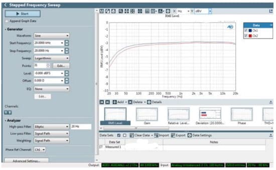
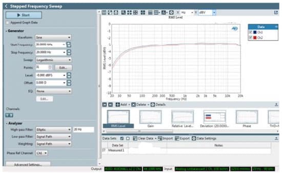
Stepped Frequency Sweep
Four groups of F980G227MSA were selected with different ranges of values for ESR. Stepped frequency response tests were conducted for each group, as shown in the following figures. The first and second groups have similar ESR values. The third and fourth groups have larger differences in ESR values.
The closer ESR values result in closer RMS values between the left and right channels. Conversely, a greater ESR difference resulted in an RMS difference between the left and right
channels of around 1 dB at low frequencies.

F98 and F38 Tantalum Capacitor Options
Analyzing the effects of ESR and capacitance for DC blocking capacitors in audio signal paths demonstrates how critical they can be for high-fidelity applications. Unfortunately, optimal capacitor selection may not be possible when constrained by height, size, and cost. Therefore, it is recommended that the designer first maximize capacitance by using a high CV tantalum capacitors such as F98 series.
Depending to the need of application, lower ESR option is available by tantalum polymer capacitor such as KYOCERA AVX’s F38 series. After this selection is made, designers can optimize the specific device for ESR to maximize audio performance across the dynamic range and frequency response.

