
This article based on Knowles Precision Devices blog explains role of EMI Filters in power electronics.
As power conversion systems evolve to leverage higher voltages and wide bandgap semiconductors like silicon carbide (SiC) and gallium nitride (GaN), system designers face new challenges in managing the electromagnetic interference (EMI) frequency landscape. Here’s how EMI filters play an important role in ensuring safe operation at higher voltages.
The Role of EMI Filters in Power Electronics
EMI filters are designed to keep internally generated electrical noise from conducting across the system and negatively impacting operations elsewhere. In other words, they contain and manage noise. In power electronics, they take the form of power line filters that protect the line from upstream noise.
While the list may differ depending on system requirements, the core components of a power line filter include:
- A common-mode filter circuit with two or more line-to-chassis capacitors and a common-mode inductor
- A differential mode (DM) filter circuit with at least one pair of series inductors and one line-to-line capacitor
- Compensation networks to adjust the filter’s quality (Q) factor and adapt the output impedance as needed
- Transient voltage suppression device(s) to defend against surges
Figure 1 shows an EMI filter structure that could be useful for single-phase AC applications or for DC power inputs.
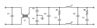
L1, a common-mode choke, suppresses EMI and improves signal integrity. L1, C5 and C6 work together to manage second-order losses. C5 and C6 are commonly known as Y capacitors. L2 and L3 are the two inductors that form the differential-mode inductance. C1, C2 and C4, also known as X capacitors, are line-to-line capacitors for differential-mode loss. With common- and differential-mode losses and two RC shunt networks (R1, C3 and R2, C7), quality factor and output impedance are controllable.
Normal/Differential Mode vs. Common Mode
Differential-mode, or normal-mode, noise is a voltage differential that appears between the power line and a neutral or return line, where power naturally flows through an electric circuit. These currents travel in opposite directions on the circuit’s conductors. Normal-mode transients have a direct path through the circuit, so, naturally, they have an opportunity to degrade system performance.
Power supplies and motor controls that leverage high-frequency switching, like pulse width modulation (PWM) motor controls, are major differential-mode noise contributors. For example, with PWM controls, switching creates differential-mode noise at the source because of high ripple currents in DC link capacitors.
Alternatively, common-mode currents travel in the same direction on the circuit’s conductors, so they return on a separate path. This kind of noise is more common between ground and two normal-mode lines. Since this type of noise is more common on more lines, it’s cause for concern; analog and digital circuits are susceptible to poor function and failure. Common-mode noise tends to be higher frequency than differential-mode noise because it originates from capacitive coupling. Higher frequency leads to coupling between components and lines. More coupling, more common-node noise.
The Role of Safety Capacitors in EMI Filter Circuits for Power Electronics
X capacitors and Y capacitors, identified in the description of Figure 1, are designated safety capacitors. Since they’re exposed to hazardous voltages more than other components, certification ensures that they’ll operate efficiently and safely under more extreme conditions.
Class-X and Class-Y capacitors minimize EMI in different applications. Class-X, or “across-the-line” capacitors, are placed between wires carrying AC current to prevent shock in the event of failure. Class-Y capacitors, or “line-to-ground” capacitors, offer line-to-ground protection and are rigorously tested to minimize shock risk in the event of a ground failure. X1/Y1 safety capacitors combine both classes and can function appropriately regardless of where they’re placed in the circuit.

