
Many factors increase the amount of “noise” interference that can damage or disturb the functionality of electronic devices.
Today’s automobiles are a prime example. In a single vehicle, you can find Wi-Fi, Bluetooth, satellite radio, GPS systems, and that’s just the beginning. To manage this noise interference, the industry typically uses shielding along with EMI filters to eliminate unwanted noise. But now some of the traditional solutions for eliminating EMI/RFI are no longer sufficient.
This issue is leading many OEMs to avoid options such as 2-capacitor differential, 3-capacitor (one X-cap and 2 Y-caps), feed-through filters, common mode chokes, or combinations of these for more suitable solutions such as monolithic EMI filters that have better noise suppression in a smaller package.
When electronic devices receive strong electromagnetic waves, unwanted electric currents can be induced in the circuit and cause unintended operations — or interfere with intended operations.
EMI/RFI can be in the form of conducted or radiated emissions. When EMI is conducted, it means the noise travels along the electrical conductors. Radiated EMI occurs when noise travels through the air as magnetic fields or radio waves.
Even if the energy applied from the outside is small, if it is mixed with the radio waves used for broadcasting and communication, it can cause loss of reception, abnormal noise in sound, or disrupted video. If the energy is too powerful, electronic devices can be damaged.
Sources include natural noise like electrostatic discharge, lighting, and other sources and artificial noise such as contact noise, leaking devices that use high frequencies, unwanted emission, and others. Usually, EMI/RFI noise is common mode noise, so the solution is to eliminate unwanted high frequencies with an EMI filter, either as a separate device or embedded in circuit boards.
EMI filters
EMI filters typically consist of passive components, such as capacitors and inductors, connected to form circuits.
“The inductors allow dc or low-frequency currents to pass through while blocking the harmful unwanted high-frequency currents. The capacitors provide a low-impedance path to divert the high frequency noise away from the input of the filter, either back into the power supply or to the ground connection,” says Christophe Cambrelin of Johanson Dielectrics, a company that manufactures multilayer ceramic capacitors and EMI filters.
Traditional common mode filtering approaches include low pass filters using capacitors that pass signals with a frequency lower than a selected cutoff frequency and attenuates signals with frequencies higher than the cutoff frequency.
A common starting point is to apply a pair of capacitors in a differential configuration, with one capacitor between each trace and ground of the differential input. The capacitive filter in each leg diverts EMI/RFI to ground above a specified cut-off frequency. Because this configuration involves sending a signal that is opposite in phase through two wires, the signal-to-noise ratio is improved while unwanted noise is sent to ground.
“Unfortunately, the capacitance value of an MLCC with X7R dielectric (typically used for this function), varies significantly with time, bias voltage, and temperature,” says Cambrelin.
“So even if the two capacitors are tightly matched at room temperature, with a low voltage, at a given time, it very likely that they end up with a very different value once time, or voltage, or temperature have changed. This mismatch between the two lines will cause the response near the filter cut-off to be unequal. Therefore, it will convert common mode noise to differential noise.”
Another solution is to bridge a large value ‘X’ capacitor across the two ‘Y’ capacitors. The ‘X’ capacitor shunt delivers the desired effect of common mode balancing, however, with the undesired side effect of differential signal filtering. Perhaps the most common solution and an alternative to low-pass filters is the common mode choke.
A common mode choke is a 1:1 transformer where both windings act as both primary and secondary. In this approach, current through one winding induces an opposing current in the other winding. Unfortunately, common mode chokes are also heavy, expensive, and subject to vibration induced failure.
Still, a suitable common mode choke with perfect matching and coupling between the windings is transparent to differential signals and presents high impedance to common mode noise. One disadvantage of common mode chokes is the limited frequency range due to parasitic capacitance. For a given core material, the higher the inductance used to obtain lower frequency filtering, the greater the number of turns required and consequent parasitic capacitance that defeats high-frequency filtering.
Mismatch between windings from mechanical manufacturing tolerance can cause mode conversion, where a percentage of the signal energy converts to common mode noise and vice-versa. This scenario elicits electromagnetic compatibility and immunity issues. Mismatches also reduce the effective inductance in each leg.
Regardless, common mode chokes do have a significant advantage over other options when differential signals (to pass) operate in the same frequency range as the common mode noise that must be suppressed. With a common mode choke, the signal pass band can extend into the common mode reject band.
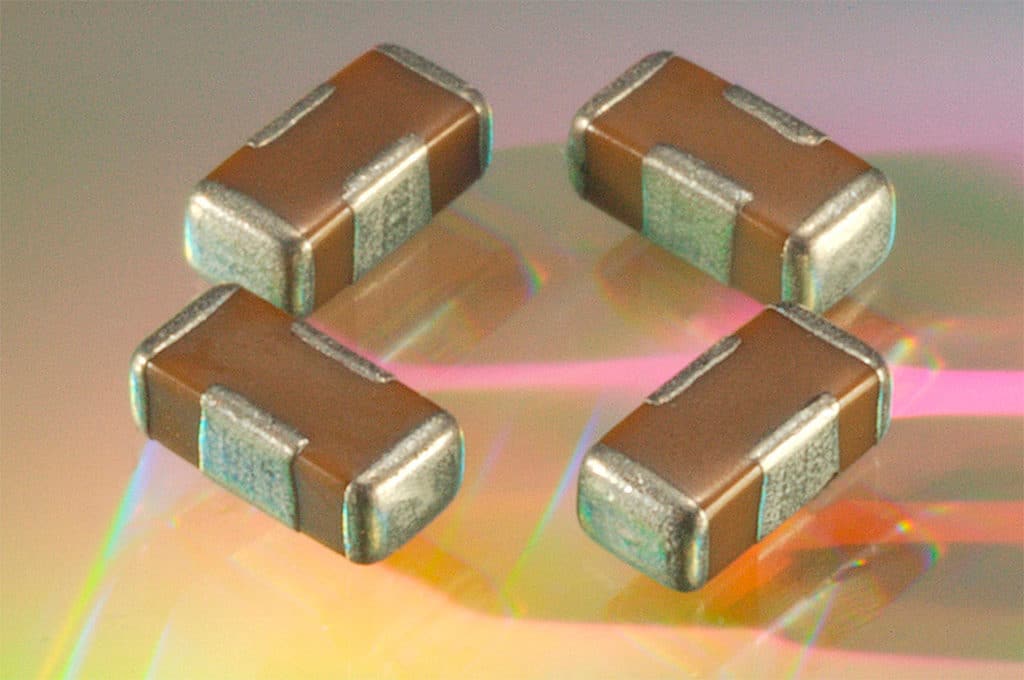
Monolithic EMI filters
Despite the popularity of common mode chokes, an alternative may be monolithic EMI filters. When properly laid out, those multilayer ceramic components provide excellent rejection of common mode noise. They combine two balanced shunt capacitors in a single package, with mutual inductance cancellation and shielding effect. These filters use two separate electrical pathways within a single device attached to four external connections.
To prevent confusion, it should be noted that a monolithic EMI filter is not a traditional feed-thru capacitor. Although they look identical (same package and external look), their design is very different, and they are not connected in the same way. Like other EMI filters, monolithic EMI filters attenuate all energy above a specified cut-off frequency and only selecting to pass required signal energy while diverting unwanted noise to “ground.”
The key, however, is the very low inductance and matched impedance. With monolithic EMI filters, the terminations connect internally to a common reference (shield) electrode within the device, and the plates are separated by the reference electrode. Electrostatically, the three electrical nodes are formed by two capacitive halves that share common reference electrodes all contained in a single ceramic body.
The balance between capacitor halves also means piezo-electric effects are equal and opposite, canceling out. This relationhsip also affects temperature and voltage variation, so components age equally on both lines. If there is a downside to these monolithic EMI filters, it is that they cannot be used if the common mode noise is at the same frequency as the differential signal. “When this is the case, the common mode choke is a better solution,” says Cambrelin.
featured image source: Johanson Dielectrics

