Source: Original EPCI article
by: Tomas Zednicek, EPCI
MLCC capacitors are dominating today’s capacitor market enabling high grade of electronics miniaturization. The continuous downsizing and use of higher and higher dielectric constant materials for MLCC class II capacitors has however resulted in worsening of some electrical parameters stability such as capacitance drop at operating conditions. Thus, in consequence, what can be considered as an enabling technology for consumer and wearable applications may pose some risk if used in critical applications such as automotive, safety, medical or industrial sector, that are also in need for continuous miniaturization.
Understanding of this behaviour in the worst case application conditions is necessary for reliable designs. In many cases, capacitance loss data available from MLCC manufacturers are given as “typical” performance leaving responsibility for “guaranteed” operation to the electronic system designer. Aim of this article is to explain it basics, provide some guidelines on MLCC class II capacitance loss phenomenon, suggest some design rules & recommendations and initiate discussion within the passive components industry on suitable DC BIAS Capacitance loss reference “guaranteed” conditions.
The next PCNS 2019 Passive Components Networking Symposium that will be held September 10-13th, 2019 in Bucharest, Romania will introduce MLCC Class II DC BIAS & Ageing Capacitance Loss as the Hot Panel Discussion Topic inviting representatives from MLCC manufacturers and end users to join the round table open discussion.
Chicago 2019 Winter Lesson
The Chicago 2019 snow storms and extreme cold weather heavy loaded the local infrastructure and impacted many “unexpected” aspects towards the people everyday lives. There are some warnings and lessons to learn out of this. For example, output from regenerative energy sources solar and wind power was close to zero leaving the existing electric power supply network infrastructure in short supply, not sufficient to meet the peak energy demands.
In electronic sector, the severe weather conditions clearly distinguish between the “good” and “bad” designs of outside environment operating devices. Lips are not moving for a long time at -40C and strong cold wind, so short mobile talk time outside does not hurt so much, nevertheless industrial, safety, infrastructure or automotive systems are required to work reliably, as usual.
We are just entering era of autonomous devices that will have to process more than 4TB of data per day with its sufficient computing power even at Chicago 2019 winter type of weather. It is clear, for example, that sensors and radar electronics directly faced to the outside environment will have to avoid collisions “without excuse” even in such extreme conditions (that under global warming effect may be seen even more often).
There is a clear need for miniaturization in automotive and other “higher reliability” electronics, but copy and paste approach of some “extreme” designs approaches used in consumer electronics may lead to critical failures there. MLCC class II capacitors with typically high level of electrical parameter dependency can be one of the component for attention. Passive component industry has to pick its piece of responsibility to provide assistance and help with correct guidelines, provide alternative solutions, clear design rules and referenced “guaranteed” performance specification.
MLCC DC BIAS / AC Voltage & Ageing Capacitance Loss Explained
Ceramic capacitors mostly used in electronics can be split into two main classes of capacitors (see Table 1 and Table 2 below):
- Class I – low loss dielectric capacitors with very stable performance but significantly lower capacitance values (no Cap Loss issue and not the main subject of this article)
- Class II – high dielectric constant but high loss dielectrics
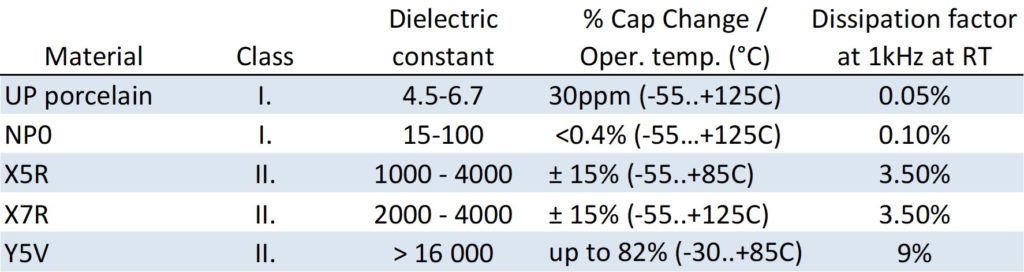

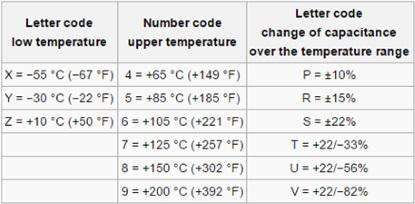

Table 2. MLCC Class 2 ceramic capacitors code system following EIA RS-198
The MLCC class II capacitors are using BaTiO3 ferroelectric materials as a high dielectric constant material to achieve its very high capacitance values in small dimensions. Downside of this material is its strong dependency on operating conditions – namely loss of capacitance – with DC Voltage (DC BIAS), AC Voltage, temperature and ageing with time. In addition, piezo noise may degrade smoothing capabilities of these capacitors at certain condition.
1.MLCC Capacitance Ageing with Time
BaTiO3 has a cubic crystal structure above the Curie temperature (approx 125°C or more), but below the Curie temperature it turn into a different crystal structure (tetragonal) that creates a dipole, respectively domains of dipoles with different dipole orientations that reduces its original polarization and thus reduces its capacitance values (spontaneous polarization, no voltage applied). The dielectric grain size/shape/distribution may impact number of dipoles and domains and thus the level of capacitance loss. As this structure changes with time, dielectric constant is reduced and over time, the capacitance will continue to decline.
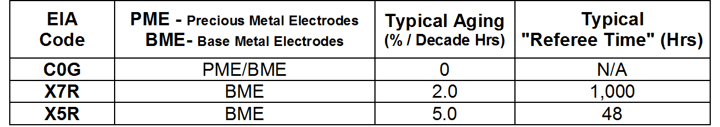

Table 3. MLCC typical aging and referee time. source: Kemet

Capacitance Ageing effect depends to MLCC dielectric type and it is constant per time decade (so the process slow down exponentially). Typical values see Table 3 above.
As the capacitance decrease with time and its important to remove some of the other “short term” mechanisms impacts, the reference time for capacitance value reading and its tolerances is set with some time delay.
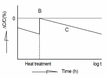
Various manufacturers use different time, but the most common reference points are 48 or 1kHz as also shown in table 3. with note that in reality manufacturers are measuring capacitance with one day or twenty-four hours after “last heat” that is also in accordance to MIL specification conditions. (Re)heating to Curie temperature “reset” the structure and returns capacitance value to its initial value as shown in Fig.1.
Fig. 1. MLCC class II capacitance loss with time and heat treatment to Curie temperature “reset”; source: Kyocera
2. MLCC Capacitance with Temperature
Depending to the dielectric type, capacitance change with temperature – see Fig.1. This is well defined per international standards and even the dielectric class is indicating the temperature stability including its tolerance field as shown in Table 1.
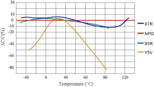

Fig 1. Capacitance change with temperature for selected ceramic dielectric types; source: Wikipedia
3. MLCC Class II Capacitance with DC BIAS
Some of the BaTiO3 dipoles are blocked by DC voltage and it can not move further with small AC voltage changes resulting in loss of capacitance. Capacitance loss due to DC BIAS is the most important contributor for real capacitance value at the operating conditions.
The level of Capacitance loss (number of blocked dipoles) is proportional to the DC field (V/mm), thus capacitor with thinner dielectric and higher volts per dielectric thickness exposure will exhibit higher capacitance loss with DC BIAS. Type and structure of the dielectric (grain size, shape, distribution, impurities) may have also a significant impact to the capacitance loss level.
In consequence, the capacitance loss level may increase with higher CV density (high capacitance in small dimensions) and it may be part number and manufacturer specific. See figure 2. below as an example of 10μF 6.3V MLCC X7R 0805 case capacitance loss with DC BIAS differences between three manufacturers. The loss at rated voltage can vary from -35% to -65% and even at more likely used derated conditions at 3.3V it can be from -12 to -32%, that may result in quite significant in-circuit performance among different manufacturers.
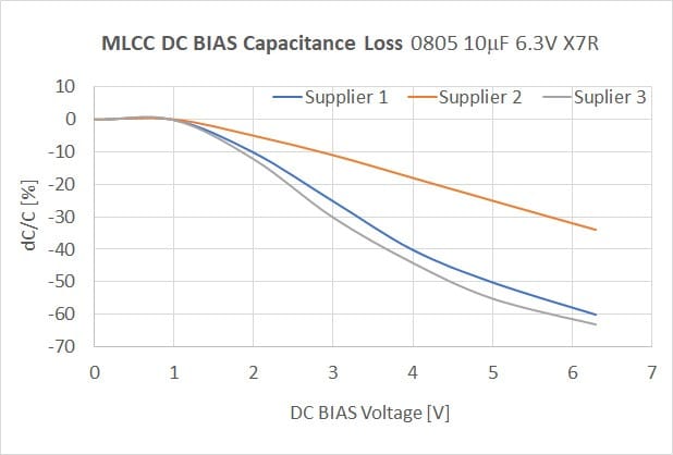

Figure 2. Capacitance loss with DC BIAS on 10μF 6.3V MLCC X7R 0805 case by three different vendors; source: EPCI using manufacturers’ datasheets
It may be of critical importance to evaluate such characteristics when qualifying alternative MLCC manufacturer under the current tight supply market situation.
The drop of capacitance due to DC BIAS is not happening immediately, but some time is needed for slower dipoles to be completely blocked. Thus, we can see some fast immediate drop of capacitance at time close to zero after DC Voltage plug in, and some additional drop within tenth of minutes to hour(s) to get to final capacitance drop level. See Figure 3.
Once all dipoles are blocked there is no further significant impact of DC voltage in longer time-frame. The capacitance value still continue to decrease per every decade by spontaneous polarisation as discussed in chapter 1., but this phenomenon is not linked to applied DC voltage. MLCC manufacturers use to talk about behaviour of the capacitor in decades … so what happens in first decade, second decade etc. as this is directly link to physical mechanisms and its impact to overall performance.
Example of the capacitance drop with time can be seen in Figure 3. sourced by Panasonic in their example of tantalum polymer capacitance stability versus MLCC.
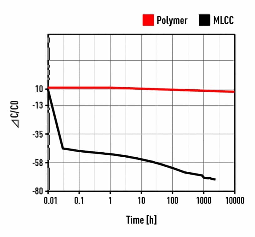

Figure 3. Capacitance drop with time under DC Voltage BIAS; source: Panasonic
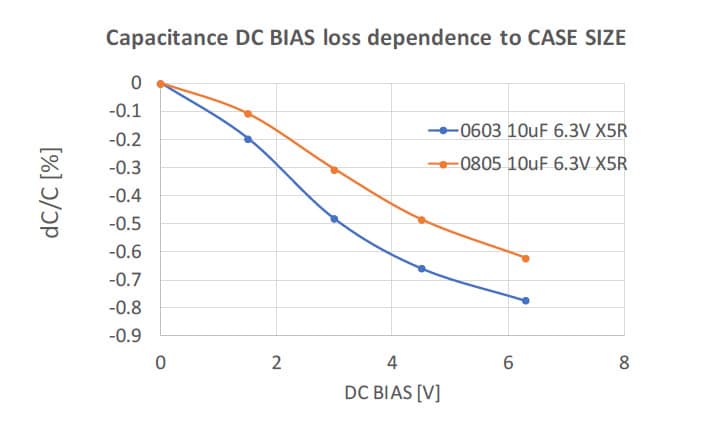
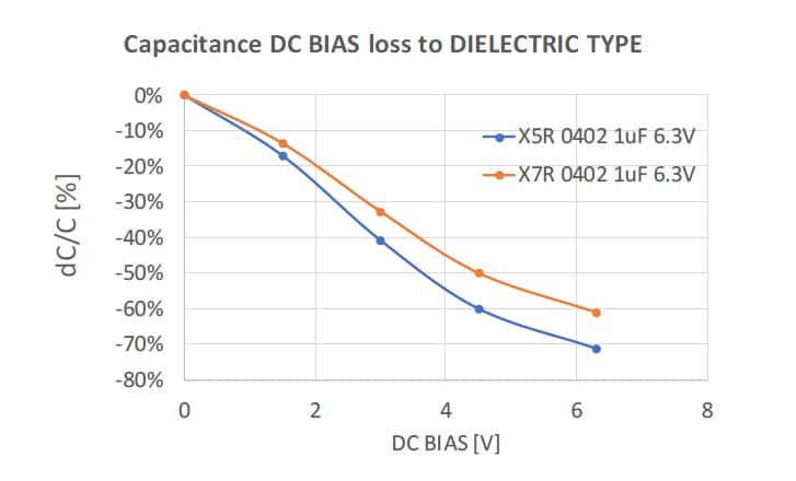
The Capacitance loss with DC BIAS effect can be reduced by using a physically larger case size design that reduces V/mm electrical field exposed to the dielectric. See Fig.4 as an example of capacitance loss with DC BIAS voltage comparison on 10μF 6.3V X5R between 0805 and 0603 case sizes. Another choice, if applicable, is to use a higher grade dielectric type material such as moving from X5R to X7R or X7R to X8R or tighter tolerance field e.g. moving from X7R to X7P types (as per Table 2.). See Fig.5 as an example of capacitance loss with DC BIAS on 1uF 6.3V 0402 capacitor comparison between X5R and X7R types.


4. MLCC Class II Capacitance with AC Voltage
Ferroelectric materials (BaTiO3) exhibit some hysteresis in polarization as a function of electric field that is causing MLCC capacitance dependency also to AC voltage. The level depends mainly to the the dielectric type as shown in Figure 6.
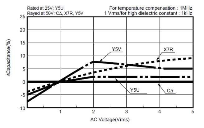

Figure 6. Capacitance change with AC voltage by different dielectric types; source: Murata
The reference standard capacitor AC volt measure conditions are set to 1Vrms at 1kHz and room temperature. Nevertheless, there are number of MLCC capacitor applications that are operating at significantly lower AC voltage such as 10mV. In this case we can expect capacitance drop of capacitance due to the small AC voltage in range of additional -5 to -15%.
The “AC voltage hysteresis” is also “re-settable” by heating of the capacitor to Curie temperature.
5. MLCC piezzo noise
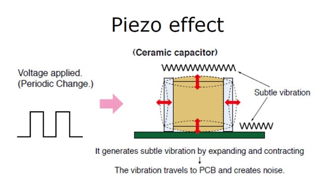

MLCC II BaTiO3 ferroelectric high permittivity dielectric is exhibiting a piezo effect. The Titanium molecule oscillates under external stresses back and forth. Electric signals can mechanically distort the dielectric. This distortion, or movement, creates a characteristic “buzzing” noise. The effect is used for microphones, piezo sensors etc. but its unwanted for capacitors where it can degrades the signal purity or creates an additional noise. The piezo effect increase with DC BIAS voltage and DC field (v/mm) stress. (thus the parts with highest DC BIAS Cap loss may exhibit also stronger piezo noise). The worst frequency range for piezo effect to happen is between 1 to 10kHz that is typical for example for LED backlight drivers, where use of high CV MLCCs shall be carefully evaluated.
Figure 7. MLCC piezo effect illustration, source: Panasonic
6. Summary of MLCC class II capacitance loss behaviour in operating conditions.
MLCC class II capacitors are offering very high level of energy density in miniature sizes that is enabling wide range of modern digital devices. On the other hand, the high capacitance density is “compensated” by inferior electrical parameters that may or may not be critical in the specific application area.
There is an multiplication effect of operating conditions that may cause significant loss of capacitance on MLCC Class II capacitors in real application conditions.
for example – if you select a X5R 0805 10uF 6.3V capacitor as 5V coupling capacitor in operating amplifier the capacitor may exhibit (depending to manufacturer):
- -60% drop of capacitance due to DC voltage 5V close to 6.3V maximum rated voltage (as per typical data provided by manufacturer)
- -15% drop of capacitance due to AC voltage being 10mV (as per typical data provided by manufacturer)
- -10% drop of capacitance due to operating temperature (as per specification sheet)
- -5% drop of capacitance each time decade (as per specification sheet)
In such operating conditions the real capacitance value can be as low as 10% of its capacitance rated value that designers of electronic devices has to count with. It is always good to check the manufacturer datasheets and its specification. Leading MLCC manufacturers are in addition providing more or less sophisticated simulation models, where designers can enter its operating conditions and the software will generate typical plots on the selected part.
Nevertheless, the issue with “typical” performance data is still there. Especially, the Capacitance loss with DC BIAS is missing its reference “guaranteed” point that can be used to make sure that the electronic device will be 100% operational even at extreme conditions such as Chicago winter.
See the next recommendation “what to do” that I would like to open for discussion among the passive component manufacturers and the electronic manufacturers during the next PCNS panel discussion in September 2019.
Recommendation How to Specify MLCC class II DC BIAS Capacitance loss
The following steps for definition of MLCC class II capacitance loss can be considered for future specification:
Procurement specification to be agreed between customer and supplier:
Capacitance loss guaranteed not to exceed XX%(for example -70%)1 at 100%2 of rated voltage, measured at reference conditions: after 12hrs3 post last de-ageing and DC BIAS voltage applied at least for 10hrs4 at RT, 1kHz and 1VAC.
the supplier shall also provide typical Capacitance loss with DC BIAS charts or link to an on-line simulation tool. Such specification would help designers to see some fixed capacitance loss guaranteed working point and evaluate the worst case at the edge operating conditions.
Customer Designer Guidelines:
If you discover that a particular capacitor is unsuitable due to capacitance loss as defined in the specification above, you have the following options:
- You can check if lower Capacitance DC loss / piezo suppression series is available by a manufacturer (need check with purchasing team as this can be more expensive part or single source)
- Use a larger capacitance value so that when the capacitance loss is taken into account, you still have enough capacitance for the required functionality. Note: higher values may have even worse DC bias characteristics due to even higher CV factor. This also may be an issue of distortion in large-signal AC, and likely will just make the problem worse and may not lead to the problem solving.
- Use a physically larger package size. This would reduce V/mm electrical stress and thus reduces also DC BIAS capacitance loss dependency. So, if you have sufficient room in your design, moving one step up in case size, for example from 0402 to 0603, 0603 to 0805 or a 1210 will significantly reduce the issue.
- If applicable you can consider to use more stable dielectric type such as moving from X5R to X7R, from X7R to X8R dielectric type or tighter tolerance field such as from X7R to X7P types. (multi-sourcing and price increase options to be checked)
- Use a different capacitor type. Sometimes, you won’t be able to escape the DC bias issue or piezo issues at all. In this case, consider looking at a different capacitor type, such as an aluminum hybrid if you have enough board space or a tantalum polymer capacitors that may provide low profile, high CV and stable option.
Notes:
- The level of defined maximum capacitance loss may be a part number specific, the actual value or some more detail guideline, if possible to introduce some general rules to be discussed with manufacturers.
- The cap loss reference DC BIAS is suggested to 100% of rated voltage, but it can be changed upon discussion with manufacturers. If suppliers are pushed to “legally” guarantee the worst capacitance drop, they will have to 100% measure and screen their production. The standard way of mass production 100% electrical capacitance measurement today is by CLR measure bridge with small BIAS 1-2V. There are two ways to measure capacitance at higher BIAS voltage:
- use of external BIAS source with CLR measurement bridge or
- indirect capacitance measurement – from I=C*dV/dt, for example to use IR measurement with 100%Vr charging for capacitance calculation and correlate it to the CAP loss characteristicsthe best fit method with low introduction cost, consistent correlation and quick implementation to be discussion with capacitor manufacturers, as one of the target for panel discussion.
3. 12 or 24hrs measurement after last heat/deaging is a standard time used also in MIL standards to define state of the dielectric after the last “reset”
4. 10hours of DC applied as reference selected in respect to decades behaviour references that is used by MLCC manufacturers … what is happening in first, second, third decade …etc. 1hour may not be sufficient in some cases to see all slow polarization to happen and need to add some safety, thus 10hours (or more) is set as the reference point.
Important note: the above recommendation is presented as a draft proposal with purpose to initiate discussion between end customers and MLCC manufacturers. The aim is to prevent critical failures in higher reliability, harsh applications that are in need for continuous downsizing and use of high CV MLCC capacitors.
Manufactures and users are welcome to join MLCC DC BIAS Voltage Hot Panel Discussion as part of the PCNS Passive Components Networking Symposium in September 10-13th in Bucharest, Romania.
more 2nd PCNS symposium technical papers can be viewed and downloaded in pdf from EPCI Academy e-Proceedings: