
This blog article written by Ron Demcko, Ashley Stanziola and Daniel West, KYOCERA-AVX Components Corporation demonstrates how use of supercapacitors can improve small-scale energy harvestor power quality.
To expand portable electronics usage/reach/offering, the renewable power industry has taken an interest in the worldwide awareness of climate change and electronic waste, specifically how batteries affect the environment. One advancement is the emergence of modern low power hand crank generators, which roughly coincides with the accelerating interest in green energy used in portable electronics.
Though other energy harvesting & generation sources are available, modern small hand crank generators are readily available at attractive prices. These simple, low power devices address a growing demand from outdoor enthusiasts to emergency use applications. Like several other harvesting sources, hand crank generators experience similar drawbacks, primarily how the output voltage can vary dramatically, depending on the consistency of the harvesting input.
This study will concentrate on the impact of SuperCapacitors used to store a generator’s raw output voltage, prior to the final voltage conditioning & regulating circuit. The results of this study are applicable to all types of small-scale energy harvesting & generation methods that encounter fluctuating input energy levels.
Introduction
From an end-user point of view, hand crank generators are attractive because they can, theoretically, provide power 24/7, as long as there is available manpower to turn the generator crank. The most common designs employ a hand crank lever which is connected to a plenary gear that then spins a ‘turbine’ shaft at a higher RPM than the crank. Rare earth element magnets are used inside the generator core to provide high power levels in a miniature sized package. The generator used for this study is a particularly well accepted hand crank generator model that produces 20 watts of power and comes in a metal case that is less than 1400 cc in volume and less than 1 Kg in weight. The generator is produced in high volumes and cost ~50 dollars.
Typically, this class of generators have multiple fixed voltage USB ports and one or more adjustable output voltage jacks, that range from 15V to 3.3V. The ability to choose the output voltages makes the standard unit capable of powering devices such as, low power RF transceivers, LED lighting, PDAs, cameras, and light tools. Furthermore, manufacturers claim the device is effective in charging lithium ion, NiMH and lead acid batteries.
Stock Generator & Initial Tests
Since the output voltage will vary depending on the speed of the crank, manufacturers of these hand crank generators recommend that end-users find the optimum RPM level by experimenting with turning the crank at a constant speed. This recommendation is due to the generator’s power conversion circuit using small holdup capacitors, on the regulators input/output. With varying speed, the small, wet aluminum electrolytic, holdup capacitors are unable to store the energy needed to stabilize the voltage through charge fluctuations.
Simply put, the output power is extremely reliant on the crank velocity. If the crank speed deviates from the optimal rotation the output voltage will immediately drop, resulting in some loads e.g., cell phones, to automatically switch its charging mode to minimum power charging. This switch will require more charging time for the loads.
Even though this type of voltage regulation is inexpensive and adequate, it requires users to match the input requirements of the regulator and the output load by optimizing the RPM through trial and error. Additionally, the crank speed will vary depending upon the generators output load, which can make finding the optimal RPM more complicated.
Essentially, small hand crank generators provide acceptable performance for most low-end loads such as LED lighting, small motors such as fans or pumps. Like other harvesting sources, these generators do have their disadvantages. However, it is easy to counteract the drawbacks by upgrading the generator with new stages and I/O components. Modifying the generator with lowcost SuperCapacitors and miniature conductive polymer / hybrid aluminum electrolytics will greatly enhance the quality and consistency of the output voltage to the load. With these small changes, the stock hand crank generator becomes a high-performance power source.
Initial Test with the Original Crank System
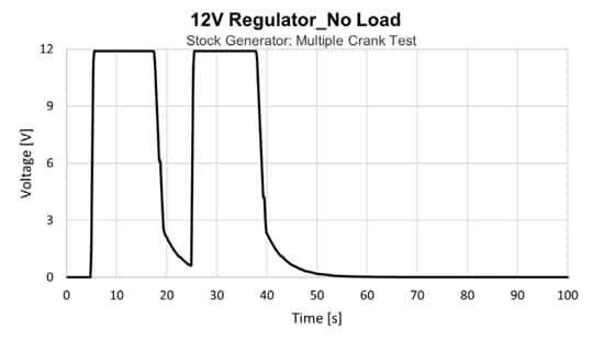
An example of output voltage drop due to crank velocity change is shown in Figure 1. This set of tests is performed by turning the generator’s crank at a constant speed, regardless of the load, and was implemented for 10 seconds during the 5 to 15 second and 25 to 35 second mark from the start time.
The first part of the test was to gauge the speed needed to maintain a constant output of 12V with no load applied. Figure 1a shows that once that rate of rotation was found, the regulated output voltage reached 12 volts and was easily maintained with a constant rotation speed. We can note that the output voltage drops to zero after the capacitors on the stock regulation circuit discharge. This is a small but notable amount of time and dependent upon the capacitance value of input/output capacitors on the regulator circuitry.
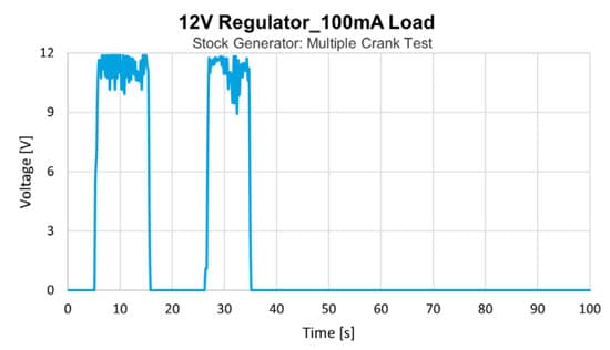
The next part of the test was to use an electronically programmable load, set to 100mA, on the generator. Adding the 100mA load, shown in Figure 1b, caused the voltage to become unstable and made the initial crank speed inadequate.
Figure 1b illustrates that the crank must turn faster to maintain charge on the input capacitors for the stock generator regulator circuit.

One way around the different crank speeds for different voltages and loads, is to crank the generator at a high rate of speed to ensure that the small capacitors on the input to the regulators are always charged. This approach works, but in reality, is quite impractical. Consider the crank being connected to a drive shaft from a micro hydro source or a set of windmill blades. The driving force is very unlikely to provide the exact speed to the crank and further the force varies. One simple alternate approach to this problem is to use supercapacitors to store the charge from the generators output and send it to a buck-boost converter on the output.
Generator Redesign with a Supercapacitor Storage Bank
The key goals when redesigning the generator were to reuse the existing box enclosure and to provide a constant output voltage independent of the crank speed. This was accomplished by changing two major designs to the stock generator. As seen in Figure 2 we added a SuperCapacitor bank between the generator’s output and the power conversion circuit. The bank was used to store the raw harvested energy from the generator and then distribute the energy to the output conversion circuitry.
The second change was to scrap the output circuitry and replace it with a wide-input-range buck-boost circuit. Since most of the generator’s end applications were 12V, it was appropriate to use a single 12V output level buck-boost power converter. In addition to replacing the output circuitry, the regulator’s input and output capacitors were upgraded.
The input capacitor was upgraded to an ultra low ESR conductive polymer aluminum electrolytic capacitor and the output capacitor was upgraded to a low ESR hybrid aluminum electrolytic. The input capacitor family was chosen based upon its ultra-low ESR, small size and wide voltage rating in a small size. The output capacitor of the regulator was upgraded to a low ESR hybrid aluminum electrolytic for its low ESR, high reliability and small size. A picture of the realization is shown in Figure 3.
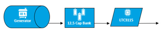
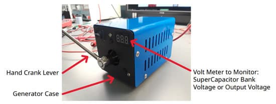
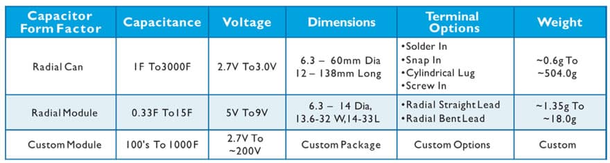
Table 1 shows the different SuperCapacitor options offered by KYOCERA AVX. The SCC series (radial can) were chosen for this study because of their high capacitance per unit volume, their ability to take hundreds of thousands of charge discharge cycles and high long-term reliability.
Additional advantages of SCC series radial package SuperCapacitors are:
• Multiple product series available
• Multiple voltage offering
• Ten different case sizes
• Highest number of capacitance values available
SuperCapacitors are commonly used in single and parallel configuration for lower voltage designs (voltages less than the rated cell voltage minus a voltage de-rating). However, for this test design, the input voltage will swing from 0 to ~18 V. In order to obtain the correct rated voltage, multiple cans must be configured in series. After review, eight 2.7V rated parts with 100 F were chosen in series to create a stack of 12.5 F at 21.6 V.
To maximize SuperCapacitor reliability, a voltage derating of 20% was applied to the capacitor stack, which gave a voltage value of 17.28V. Since the physical size constraints will not allow anything over 8 SuperCapacitors, it is unlikely to obtain a de-rated voltage higher than 17.28V.
Even though, the targeted value of 18V was missed, it is very improbable that the generator will achieve an 18V output voltage with these specific test conditions. Therefore, our design proceeded with a de-rating slightly less than 20%. This derating was deemed acceptable for this design based upon previous work by DeRose et al[1] showing SuperCapacitor reliability as a function of applied voltage and use temperature.
SuperCapacitor balancing is used to ensure long life for multiple SuperCapacitors connected in series. This is done by balancing the charge on each SuperCapacitor to prevent over-voltage damage. Multiple cans can be balanced via active or passive methods.
Active Semiconductor Balancing
Active Semiconductor Balancing is the most efficient and exacting method. Unfortunately, it has a more significant cost than passive balancing. The size required for active balance solutions varies greatly based upon the number of cells in need of
balancing as well as the size of cell/semiconductor types used in balancing.
Passive Balancing
Passive Balancing is the cheapest, smallest and the easiest method to use. However, since it’s accomplished with a resistor, a small amount of power is dissipated, reducing efficiency.
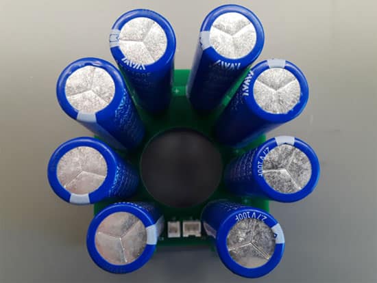
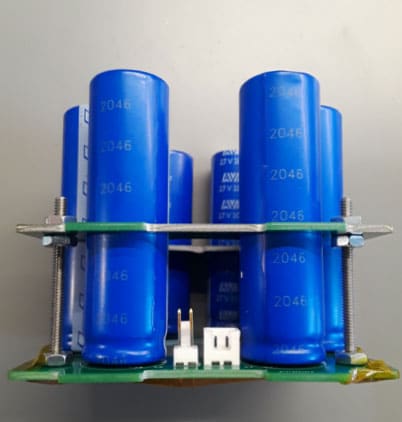
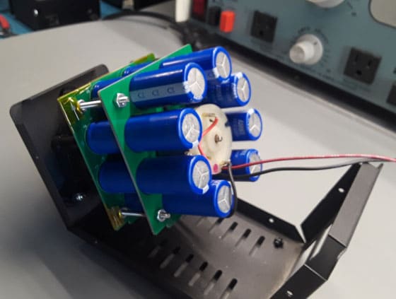
For this test, KYOCERA AVX SCCV60B107SRB was chosen for its dimensions. With a diameter of 18 mm and a length of 60mm, eight pieces were nearly the ideal physical dimensions needed to be placed around the generator core using a set of PCBs. The base PCB, shown in Figure 4a, was designed to connect the eight SuperCapacitors in series and the 10kΩ balancing resistors, producing a 12.5 F module. The second PCB was used to equally space the SuperCapacitor module around the far end of the generator. To provide extra stability for the module, both boards were mounted together with centering ears, located in the external case, shown in Figure 4b. Figure 4c shows the final installation around the generator.
Output Circuitry Redesign
An Analog Devices, LTC3115, was chosen to replace the stock generators output circuitry. This IC is a high voltage monolithic synchronous buck- boost converter with a wide allowable voltage input range of 2.7V to 40V and it has a design selectable output range from 2.7V to 40V[2]. For these tests, the output voltage needed to be set to 12V.
As previously stated, the generators rotational speed dictates its output voltage. That output voltage charges a 12.5 F SuperCapacitor bank, which goes on to power the LTC3115, shown in Figure 4. When the generator output charges the bank > 12V the converter works in a buck mode, and when the output charges the bank < 12V the converter operates in a boost mode.
Boost mode is typical during low crank rotational speeds and after the generator is no longer turning. That ‘power down’ sequence has the SuperCapacitor module providing charge to the LTC3115. Eventually, the voltage from the SuperCapacitor bank will drop below the IC’s operating voltage, causing the output to drop to zero.
There was careful consideration when replacing the input and output bulk capacitors on the LTC3115. Options for these capacitors are wet, polymer and hybrid aluminum electrolytics as shown in Table 2. For the input bulk capacitors, a KYOCERA AVX 68µF, 35V, KYOCERA AVX P/N APA0609680M035R conductive polymer aluminum was chosen as a replacement.
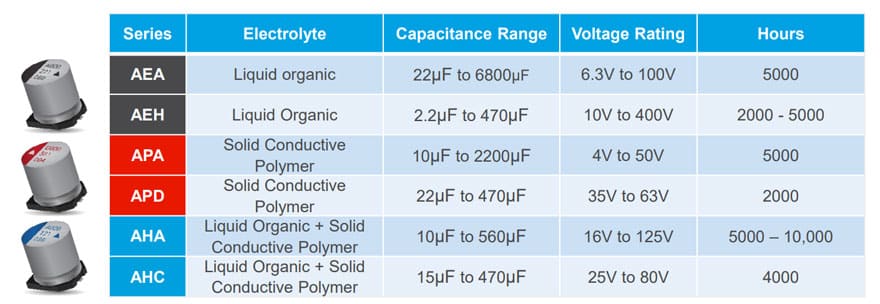
The conductive polymer was chosen because they provide low ESR, stability across temperature and high reliability[3]. The combination of these features is a significant upgrade over the original input capacitor, a traditional wet aluminum. For the output bulk capacitors, a KYOCERA AVX 27uF, 25V, KYOCERA AVX P/N AHA0608270M025R hybrid aluminum was chosen as a replacement.
Hybrid Aluminum Electrolytic capacitors offer low ESR in combination with high stability across temperature and frequency. Additionally, hybrid aluminum electrolytics have low DCL (DC Leakage), consistent self-healing and an open circuit failure mode[3]. Hybrid Aluminum Electrolytics are commonly chosen for extended reliability power conversion applications due to their size, stability, low-loss and high reliability.
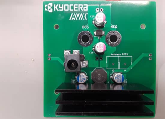
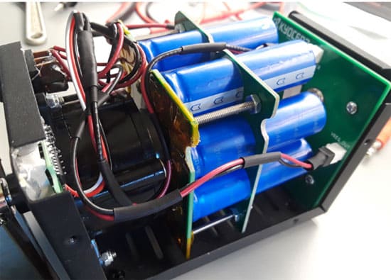
Figure 5a shows the LTC3115 buck boost board and the configuration of the Conductive Polymer (red markings) and Hybrid Aluminum Electrolytics (blue markings). Anderson power poles output connectors were not yet installed in this photo in order to get a clearer picture of the Conductive Polymer Aluminum electrolytics. Figure 5b shows the buck-boost proximity relative to the generator and case. The LTC3115 sits underneath the heat sink for added reliability. The heat sink can serve as a relative size comparison to illustrate the small size of the Conductive Polymer and hybrid Aluminum Electrolytic capacitor.
A panel mount voltmeter was installed along with a switch allowing the monitoring of the SuperCapacitor stack charge voltage or the regulated output voltage.
Redesigned Generator Testing
Data was taken after the SuperCapacitor module and the buck-boost converter were successfully installed in the existing generator enclosure. The only visible difference between the stock generator and the modified one is the front panel (switched voltage monitoring) and the back panel – single 12V output via Anderson power poles or banana jack terminals.
A direct comparison of output voltage stability between the original and redesigned generator was not exactly possible. Since the SuperCapacitor bank needed to be charged to a minimum voltage before an output could be measured, there was an unwanted discrepancy on start times. It was determined that it took ~28 seconds to achieve 12V at the crank speed determined from the initial test, and this was used as the new start time to monitor output voltage stability.
The increased stability of output voltage because of the SuperCapacitor bank providing charge to the buck-boost circuit is easily recognized. The LTC 3115 turns on as the voltage level of the SuperCapacitor bank is increased to the minimum operating voltage (~2.7V) of the chipset. The LTC 3115 operates in a boost mode between the minimum turn-on voltage and 12V. Beyond 12V the chipset goes into a buck state, but in all cases maintains the desired 12V output voltage.
The same operational states are true as the capacitor bank discharges when the generator stops providing charge. The LTC3115 operates in a buck state until the voltage drops below 12V. At that point the chipset goes into a boost mode until its minimum operating voltage (2.7V) is not met. At that point the output voltage drops to zero.
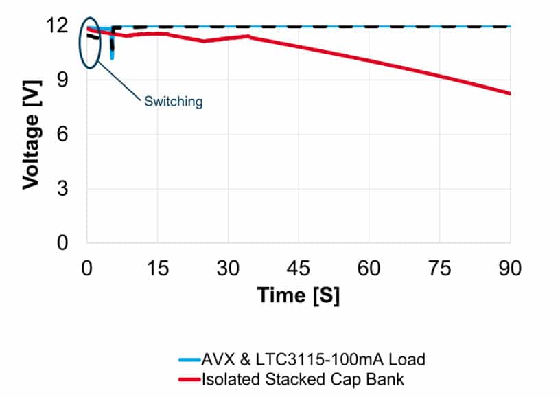
An example of the power down state – when the generator is no longer turned, and the output conversion circuitry is operating by depleting stored charge in the 12.5 F bank is shown in Figure 6. In Figure 6, the red line illustrates the 12.5 F module voltage reduction over time as it solely powers the LTC3115 during a 100mA load for approximately 90 seconds. The solid blue line represents regulated output voltage under 100mA load, and the dashed black represents the 500mA output regulated. As expected – the SuperCapacitor bank can operate both loads at the LTC 3115 output voltage for significant amounts of time even when there is no generator charging the SuperCapacitors. The SuperCapacitors will be drained since it is powering the power converter circuitry which is powering the load. When the SuperCapacitor voltage drops below the minimum operation voltage of the LTC3115, the load IC will power down and the load will then receive zero volts.
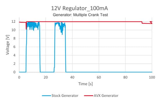
Pulsed duration tests were conducted identical to those of the stock generator. The tests for the modified generator are based upon loading the generator with 100mA and 500mA loads. Once a 12V charge level was stored, the tests proceeded as in the stock capacitor case. The crank of the generator was turned at a constant speed for both the 100mA and 500mA test during the 5 to 15 second and 25 to 35 second points in test duration.
Test results comparing the stock and modified generator are shown in Figure 7. The importance of this series of tests is to show that regulated 12V power is on the output, in all
SuperCapacitor bank charge states above the ICs minimum operating voltage.
It should be noted that the rapid drop of voltage in both the 100mA and 500 mA test is a result of switching the meter between generator output to the SuperCapacitor module, and the output regulated voltage. We are seeing switching effects of a dual pole switch.

Summary
Hand crank generators are convenient, inexpensive, and useful to power a variety of small to medium power loads, but when the output stability is independent of crank speeds,
it has implications for simple yet efficient energy harvesting and remote applications as well. The stability of output voltage in these generators has the potential to be greatly improved by using a SuperCapacitor module intended to store harvested voltage and power output conversion circuitry. A properly sized SuperCapacitor bank can store generator voltage and provide a stable & predictable voltage to a buck-boost IC.
A buck-boost chipset greatly improves output voltage conversion duration but is enhanced further with the latest in aluminum electrolytic technology. Conductive polymers are ideal as input capacitors because of their extremely low ESR and wide voltage range. Hybrids are very beneficial to the output of buck-boost circuitry due to low ESR, stability, high reliability, and small size characteristics.
This study proves that the addition of SuperCapacitors can stabilize voltage on the input side of a PMIC and thus improve & optimize the PMICs output voltage.
References
- [1] E. DeRose, “Reliability of SuperCapacitors: Long-Term Reliability Test Data (Part 2),” 2018. [Online]. Available: https://www.kyocera-avx.com/resources/reliability-of-supercapacitors-long-term-reliability-test-data/.
- [2] A. Devices, “LTC3115-1,” [Online]. Available: https://www.analog.com/en/products/ltc3115-1.html
- [3] “Aluminum Electrolytic Capacitors,” 2021. [Online]. Available: https://www.kyocera-avx.com/docs/literature/Aluminum-Capacitors-Brochure.pdf

