
IEC 60115-8 edition 3 international standard for fixed surface mount resistors specified by IEC, clarifies the relationship between the rated power and the operating temperature, while Edition 2 does not, which was achieved by fully changing the testing method to be based on the temperature of the terminal part (solder filet) of resistors. This modification enables Edition 3 to ensure the safer use of resistors.
IEC 60115-8 is an international standard for fixed surface mount resistors specified by IEC. Based on this standard, resistor manufacturers test and determine specifications such as rated power, nominal resistance value, tolerance, and temperature coefficient of resistance.
In August 2023, IEC 60115-8 was revised and published as the 3rd edition (Edition 3), introducing a new concept of reference temperature for determining rated power of resistors. This article is based on KOA tech article. KOA participated in the revision of this standard with a leadership as an advocate of terminal part temperature specification and as one of the representative companies of Japanese resistor manufacturers.
This revision creates following two benefits for customers.
- Resistors can be used more safely by knowing the terminal part temperature of surface mount resistors in operation.
- High-power resistors can be used with less mounting space by conducting proper heat dissipation using the latest cooling technology.
Surface mount resistors can be used more safely
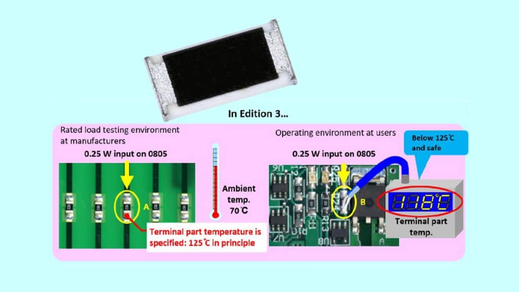
The revised standard allows resistor users to know the terminal part temperature at the time of endurance test applied with the rated power under high temperature, which is performed by resistor manufacturers to guarantee the rated power.
In this report, the terminal part temperature at the time of testing is referred to as the “rated terminal part temperature.“
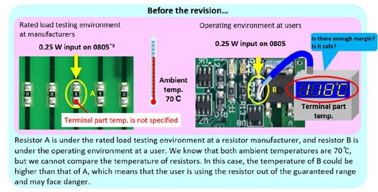
Since the previous edition did not provide the rated terminal part temperature, the users had no way of comparing the actual operating environment with the testing environment. In the revised standard, the rated terminal part temperature is unified to 125 ֯C in principle. As a result, surface mount resistors can be used more safely, as described below.

By utilizing the latest cooling technology, surface mount resistors can be used with higher rated power
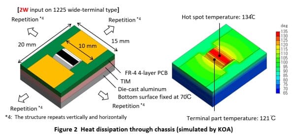
Recently, we have seen mounting forms where the bottom of PCB is thermally coupled to a water-cooled chassis via Thermal Interface Material (TIM) to increase the heat dissipation capacity of PCBs. With this type of cooling system, the terminal part temperature and the overall temperature of the resistor remain low even when the surface mount resistor consumes a large amount of power.
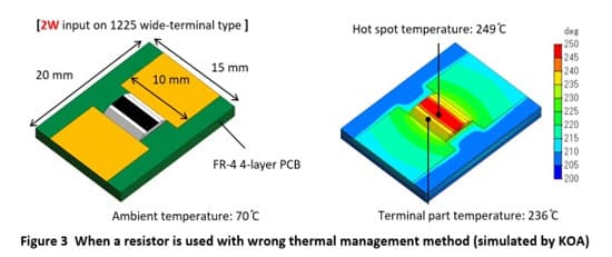
Figure 2 shows an example of the cooling system described in Annex G of the third edition of the standard. For such cases, when determining the applicability of resistors with high rated power under high-heat dissipation conditions, the use of ambient temperature as a basis is not appropriate, but the terminal part temperature is. Annex G of the revised standard describes the risks of determining the applicability of wide-terminal resistors with a high rated power based on the thermal management method described in the previous standard, which only considers the ambient temperature as an operating environment for resistors.
Acquiring SMD Power Resistor Rated Terminal Part Temperature
Rated terminal part temperature is set at 125 ֯C in principle
Table 1 shows the relationship between rated power and product size for each type of resistor when the rated terminal temperature is 125C as specified in the revised standard. The rated power for each type and size of resistor in this table is the values agreed upon by the IEC committee members as current trends at the time of revising the standard from 2019 to 2023.

Note: The rated terminal part temperature of 125 ֯C means that the resistor manufacturer used a test PCB of which terminal part temperature reached 125 ֯C during the testing performed to guarantee the rated power. This does not mean that the terminal part temperature will be 125 ֯C on a PCB selected by a user when the power shown in Table 1 is applied. Users, if planning to apply the rated power, must perform thermal design when designing a product to prevent the terminal part temperature from exceeding 125 ֯C.
Resistors in same type and size have different rated powers and rated terminal part temperatures
Resistor rated power has increased at the request of resistor user and with the technological advances. For the same resistor type and size, some products have a rated power other than those listed in Table 1. There are two ways to know the rated terminal part temperature for such products, which has been added to Annex F with this revision.
1. By reading the derating curve based on the terminal part temperature]
Resistor users can read the rated terminal part temperature from derating curves based on the terminal part temperature as shown in Fig. 4, if it is presented by the resistor manufacturer. For the derating curve shown in Fig. 4, the rated terminal part temperature of the resistor is 135 ֯C, which is the terminal part temperature at the break point where load reduction begins.

In order to comprehensibly convey the concept of terminal part temperature specification, KOA has been presenting derating curves based on the terminal part temperature as shown in Fig. 4 for all types of surface mount resistors subject to IEC 60115-8.
2. By reading the graph presented in Annex F]
For resistors with specified rated power other than those listed in Table 1, the rated terminal part temperature can be obtained from the standard. Annex F of the IEC 60115-8 Edition 3 contains graphs such as Fig. 5 for each resistor type and size. The horizontal axis shows the power applied to the resistor and the vertical axis shows the rated terminal part temperature.
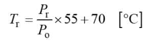
The approximate rated terminal part temperature can be calculated without using the graph presented in the standard, by applying the rated power in Table 1 to the following formula.

Why the Terminal Part and Not the Resistor Body?
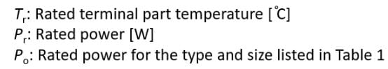
The reason for this question is described in Annex F of the Edition 3. Figure 6 shows a temperature simulation of each resistor when two 0805 resistors with different shapes are mounted on the same PCB and the same power is applied. One of the resistors has a solid film, and the other has a slit (a portion of the resistive body is removed) in the center of the film to adjust the resistance value.
The graph of the temperature distribution of the two resistors shows that the temperature distribution over the resistive body and the hottest part inside the resistor (called the hot spot) are clearly different, but the terminal part temperature is the same. As just described, the terminal part temperature is hardly affected by the structure of the resistor, thus it is suitable to be specified as the temperature management point in a standard.
Also, from the viewpoint of the temperature measurement, the terminal part is more suitable than the surface or hot spot. This is because the terminal part temperature can be measured by thermocouples even if a resistor is mounted on a PCB inside a chassis. On the other hand, the surface temperature of a surface mount resistor cannot be easily measured except with a high-resolution infrared thermograph, which cannot be used when the PCB is mounted inside the chassis. Furthermore, measuring the hot spot temperature is nearly impossible.
Reason to Focus on the Terminal Part Temperature (high power, diversifying operating environment)
Increase in the rated power of surface mount resistors in recent years
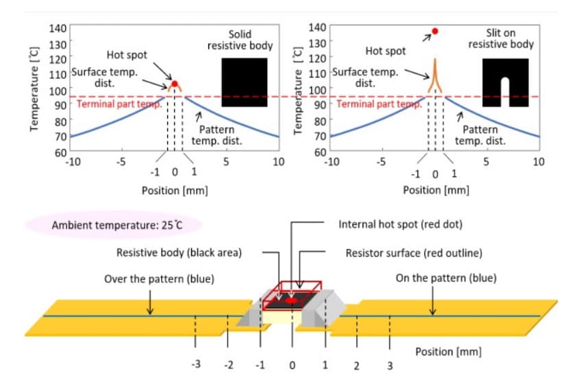
The revision has been implemented to enable surface mount resistors to be used with higher power and in the diversifying operating environment. As indicated in Fig. 7, the surface mount resistors has been gaining popularity since 1980s and their rated power has been increasing in the past few years. This increase has been supported by the heat dissipation capability of PCBs which has been advancing due to multi-layering of PCBs.
The temperature of the surface mount resistor is determined by the heat dissipation capability of the PCB on which the resistor is mounted. Using a high heat dissipation PCB, such as a multi-layer PCB, the temperature of resistor is kept significantly lower compared to using a single-sided PCB, applying the same power. It is unreasonable to specify the conventional low rated power for resistors used on multilayer PCB. With the increasing heat dissipation capability of PCBs, the rated power of resistors continues to increase. However, we must be aware of the potential danger regarding this high rated power. Since the high rated power is specified assuming the use under a high-heat dissipation condition, when the specified rated power is applied to the resistor mounted on a single-sided PCB with low heat dissipation capability, the temperature becomes extremely high. Keeping the input power at 50% of the rated power can no longer secure the safety. The resistor industry has been in need of identifying an appropriate thermal management method, regardless of the substrate to be used, to ensure the safety of surface mount resistor users.
The terminal part temperature specification is the solution.
Example of diversifying operating environment and dense mounting
In recent years, we have seen applications that have multiple surface mount resistors densely mounted. To create a similar environment, we mounted multiple 2512 resistors with a rated power of 1 W and applied a rated power at an ambient temperature of 25 ֯C for 30 minutes. Even though the resistors were used according to the derating curve, some of the resistors burned out.
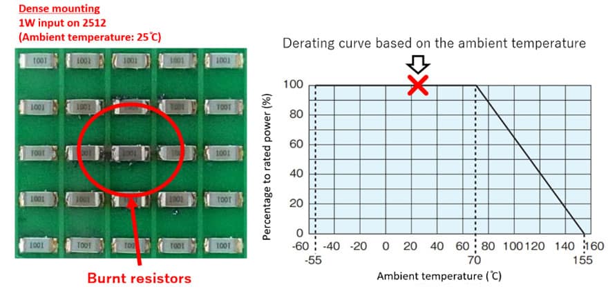
This demonstration clarifies that the conventional derating curve based on the ambient temperature may lead to misjudgment on applicability of resistors. The use of conventional derating curve based on the ambient temperature is also inappropriate for the cases in which resistors are mounted on a substrate that is attached to a chassis as described in the first part of this report. To prevent these problems, the concept of terminal part temperature specification needed to be incorporated into the standard.

