
Source: Kemet Engineering Center blog
by Ivan Quiroz. METCOM power inductors feature a metal composite powder core, which offers high current saturation characteristics that allows use with the high ripple currents found in buck converters. The high permeability of this material enables low values of DC resistance, thereby significantly reducing system losses when a METCOM inductor is used in the output stage of a DC-DC switching converter.
Consumers are adopting more and more technology into their busy lives. Whether it is the mobile devices such as tablets and smartphones that keep us connected and able to work/play anywhere or the myriad of connected devices in our homes and offices that are truly beginning to automate our environment.
The quality availability challenge
These demands require higher reliability and great sourcing partnerships. KEMET’s new line of power inductors, METCOM, offers the high-quality support KEMET is known for in our capacitors and brings them to the design table for switching regulators.

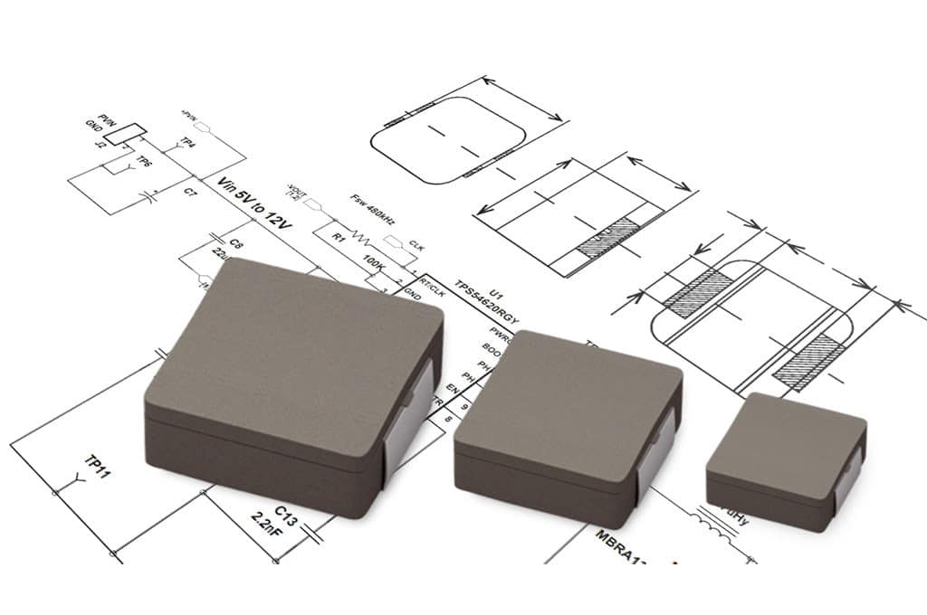
METCOM power inductors feature a metal composite powder core, which offers high current saturation characteristics that allows use with the high ripple currents found in buck converters. The high permeability of this material enables low values of DC resistance, thereby significantly reducing system losses when a METCOM inductor is used in the output stage of a DC-DC switching converter.

At the core of a switching converter, power design engineers rely on power inductors, along with the semiconductor, to operate at lower losses. KEMET’s METCOM product line allows for semiconductor designs where a high switching frequency is desired, along with a high ripple current that is stable over temperature. METCOM metal composite power inductors can support switching frequencies up to 1 Mhz, with rated currents of up to 35.4 A.

Many power solutions are in the form of ‘buck’ converters that take an input voltage and convert it down to the lower voltage required to power modern microcontrollers and processors. These buck converters can benefit from using KEMET’s METCOM MPX series to help the output inductor store energy. Further benefits can be obtained using KEMET’s KO-CAP polymer capacitors and MLCCs to smooth out the output waveform, to provide a low-ripple voltage. This check and balance of ripple current, ripple voltage, input capacitor, and output capacitor is essential to the overall design, not only from a power quality perspective, but to support safety agencies’ EMC testing.
Benefits of efficient design
The switching regulator challenge is not a new one; for years power engineers have developed switching regulators for different applications. The simplicity and reliability of buck and boost converters make them a favorite among designers. Nevertheless, while they are a very common building block, there are very specific items that need to be considered while designing with METCOM power inductors. KEMET’s METCOM MPX series offers:
- High switching frequency
- High saturation current
- High temperature
To fully take advantage of these characteristics, the design engineer must consider the following engineering tips to ensure the design passes EMI sound:
- Current Loops
- Placement matters
- Ripple Voltage
- Input Capacitor selection
- Isolation
Current Loops
When discussing the EMI aspects of a design, it is common to hear about di/dt. Which components could be generating the changes in current and how can the impact to the design be minimized? When placing METCOM inductors, it is important to take note of the current waveform that is going through the inductor and where it is coming from, in order to know where it needs to return.

In a buck converter, for example, the current changes (d ) will have either the input capacitor or the output capacitor source the energy, ensuring the input power source ripple current is reduced. The layout must consider the current path, to ensure that the current source from one component has the shortest path back to that component, minimizing the loop. A high frequency current needs to be sourced and returned to those input and output components; therefore, the layout between the semiconductor, inductor, and capacitors needs to be tightly controlled. Give special attention to the return currents’ ground, as they need to be properly laid in order to control the path current’s return to the source.
Placement Matters
Understanding topology design, and how the current flows, guides the placement of the components. When designing with a METCOM power inductor, a capacitor will always be a critical part of the system. Switching regulators can benefit from the high energy capabilities of a KO-CAP polymer capacitor and MLCC with lower ESR. The mix of both technologies will minimize the number of capacitors needed, while supporting a low ripple voltage. Placement of the capacitors, with respect to the inductor to minimize the current loop, is the initial step toward a reliable design.
Once the placement is identified, the input power traces need to be laid out, such that the inductance of the line is greater than the ESR of the input capacitors, making the input capacitor the main source of energy at the switching frequency.
Ripple Voltage
At first glance, current is king when thinking about EMI. While a design can withstand a given ripple voltage, too high a ripple voltage can translate into EMI issues further down the line.
The current switching through a METCOM power inductor has an AC component, which will flow into the output capacitance. Here, the total ESR of the output capacitance has an effect in the ripple current. The ripple voltage is a natural response to ohms low, where the current flowing into the capacitor ESR will generate a voltage. The lower the ESR, the lower the ripple voltage that is generated.
Input Capacitor Selection
When discussing input capacitor and EMI, design engineers sometimes bypass the importance of the right input capacitor. The impedance network of the input capacitors needs to be low. KEMET KO-CAP polymer capacitors can offer a low ESR version with high energy density and high ripple current capacity. A reliable design will also include MLCCs to further benefit from the low ESR at target frequencies. When selecting the input capacitor, one needs to consider that the output load current has a direct effect on the input ripple voltage. One difficulty with the initial design is sizing the transient current requirements, but such determination will have a direct impact on the input voltage and the size of the bulk capacitance for a reliable design.
Isolation
The benefits discussed thus far address the conducted emissions issues that are most frequently found due to switching power supplies. Nevertheless, on highly dense designs, radiated noise could couple into other parts of the design. KEMET offers a line of ferrite-like devices capable of absorbing the radiated energy, released as heat. KEMET’s Flex Suppressor products help the design engineer with a barrier to isolate parts of the circuit from a section that might be coupling unwanted noise.

It is easy to conclude that, while switching regulators are not a new technology, the design challenges are new to each design. KEMET’s METCOM power inductors offer solutions that couple with our capacitor offerings. This allows for designs that are supplied by KEMET’s highly reliable products, which are backed by 100 years of experience and innovation.

