
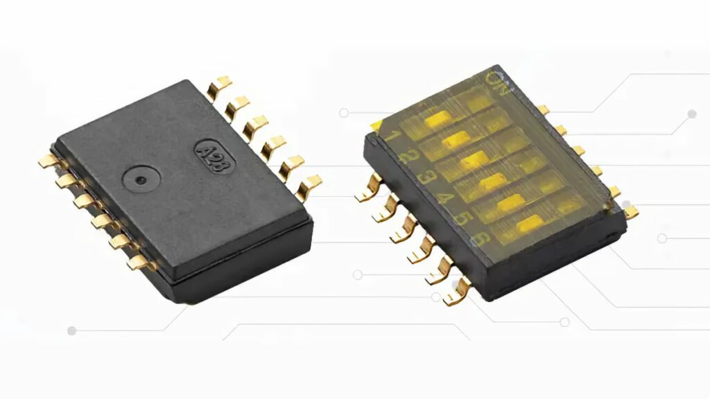
Littelfuse introduces TDB series ultra‑miniature, half‑pitch surface‑mount DIP switches that are designed for high‑density PCB layouts where space, reliability, and where automated assembly is critical.
They provide gold‑plated, washable contacts in a 1.27 mm pitch format, giving design engineers a compact way to implement configuration and address settings in low‑power control systems.
Key features and benefits
The Littelfuse TDB Series targets designers who need traditional DIP functionality in layouts that are significantly smaller than legacy through‑hole or full‑pitch SMT switches.
- Ultra‑miniature 1.27 mm half‑pitch footprint enables higher component density on crowded PCBs.
- Surface‑mount construction supports standard SMT assembly flows and automated pick‑and‑place.
- Gold‑plated bifurcated contacts provide low, stable contact resistance and improved corrosion resistance.
- Top‑tape sealed housing allows reflow soldering followed by aqueous cleaning without contaminating the internal mechanism.
- Contact ratings up to 50 V DC, 100 mA (steady state) are suitable for configuration, address and low‑power logic switching, not for power paths.
- Mechanical and electrical life of 1,000 cycles matches typical use where switches are set infrequently and left in position for long periods.
- Available in 2, 4, 6, 8, and 10 position variants, so engineers can choose just enough configuration range without wasting board area.
- Tube and tape‑and‑reel packaging options align with both prototyping and high‑volume production.
For engineers familiar with traditional DIP switches, the main benefit is achieving the same configuration behavior in far less board area, while retaining a fully serviceable, manually actuated interface.
Typical applications
The TDB Series is intended for low‑power, low‑frequency signal paths where a simple on/off or address pattern must be set during production, commissioning, or service.
- Industrial control equipment (address settings for I/O modules, node IDs, feature enable/disable).
- Power supplies and inverter systems (configuration pins, protection threshold selection, mode selection on control boards).
- Security and fire alarm systems (zone addressing, feature configuration, local overrides).
- Building automation and smoke detection equipment (bus addresses, parameter selection, commissioning settings).
- Consumer IoT and smart home devices (local configuration when no full UI is present, fallback settings during service).
A common pattern is to use a small TDB device to define address bits for a bus‑connected module, or to select between firmware modes without needing a separate connector, jumper, or programming interface.
Technical highlights
From a component selection standpoint, the TDB Series combines a small mechanical envelope with parameters optimized for signal‑level switching.
- Pitch and format
- Half‑pitch 1.27 mm contact spacing.
- Surface‑mount package optimized for reflow processes.
- Contact system
- Gold‑plated bifurcated contacts for higher contact reliability and lower risk of intermittent behavior at small currents.
- Maximum contact resistance specified in the manufacturer datasheet, suitable for logic‑level circuits.
- Electrical ratings (according to manufacturer datasheet)
- Up to 50 V DC, 100 mA steady‑state contact rating.
- Suitable for low‑power digital and control signals; not intended to switch inductive loads or mains.
- Mechanical and environmental
- Mechanical and electrical life of 1,000 actuation cycles, which is adequate for configuration switches that are not meant for frequent user interaction.
- Washable, top‑tape sealed housing supporting post‑reflow cleaning.
When designing around these switches, treat them as signal‑level configuration elements and ensure that any higher energy paths are handled by dedicated relays or solid‑state devices.
Series variants and dimensions
The series covers several position counts, trading off configuration range against PCB length:
- TDB02 – 2 positions, very small footprint for minimal configuration needs.
- TDB04 – 4 positions for basic address or mode selection.
- TDB06 – 6 positions as a compromise between density and flexibility.
- TDB08 – 8 positions for extended address or option fields.
- TDB10 – 10 positions when the maximum number of settings is required in a linear DIP format.
Body lengths follow the position count; exact values should be taken from the manufacturer datasheet and mechanical drawings when laying out the PCB.
Design‑in notes for engineers
When replacing a traditional DIP or jumper header with the TDB Series, a few layout and system‑level considerations help avoid issues in production:
- PCB layout and clearances
- Respect the 1.27 mm pitch and manufacturer‑specified land pattern to maintain solder joint reliability.
- Keep silkscreen markings clear and legible despite the smaller body; consider magnified markings or unique designators near the switch for service personnel.
- Manufacturing and cleaning
- The top‑tape seal is designed to tolerate reflow and aqueous cleaning; nonetheless, align your reflow and wash profiles with manufacturer guidance.
- If using aggressive cleaning chemistries, confirm compatibility with Littelfuse recommendations and perform qualification.
- Electrical design
- Use these switches only in low‑current, low‑voltage control circuits as defined in the datasheet.
- For very low current sensing inputs (microamp range), evaluate whether pull‑ups/pull‑downs and input filtering will tolerate the specified contact resistance and its variation over life.
- Reliability and usage profile
- The 1,000‑cycle rating is more than sufficient for production setup and occasional field reconfiguration, but not intended for daily user interaction.
- For applications where settings might be changed frequently, consider whether a different user interface (rotary encoder, push buttons, software settings) is more appropriate.
By following these guidelines, design engineers can leverage the compact TDB footprint without compromising manufacturability, testability, or long‑term field performance.
Source
This article is based on information provided in the official Littelfuse press release and associated TDB Series product documentation on the manufacturer website, with added independent commentary aimed at design engineers and component buyers.
References
- Littelfuse/C&K introduces TDB Series ultra-miniature half-pitch surface-mount DIP switches – official press release
- Littelfuse TDB Series product page

