

This article reviewing our findings on the effect of the burn-in test, a common quality control process, on the dynamics of oxygen vacancies within BME MLCC ceramic capacitors.
These findings reveal the burn-in test has a negative impact on the lifetime and reliability of BME MLCCS.
This paper by Pedram Yousefian, Ph.D. candidate at Materials Research Institute, Department of Materials Science and Engineering, Center for Dielectrics and Piezoelectrics, The Pennsylvania State University, USA was presented at the 4th PCNS 10-14th September 2023, Sønderborg, Denmark as paper No.1.4. and selected by TPC committee as:
OUTSTANDING PAPER AWARD
Abstract
Base metal electrode (BME) multilayer ceramic capacitors (MLCCs) are widely used in aerospace, medical, military, and communication applications, emphasizing the need for high reliability. The ongoing advancements in BaTiO3-based MLCC technology have facilitated further miniaturization and improved capacitive volumetric density for both low and high voltage devices. However, concerns persist regarding infant mortality failures and long-term reliability under higher fields and temperatures.
To address these concerns, a comprehensive understanding of the mechanisms underlying insulation resistance degradation is crucial. Furthermore, there is a need to develop effective screening procedures during MLCC production and improve the accuracy of mean time to failure (MTTF) predictions. This article reviews our findings on the effect of the burn-in test, a common quality control process, on the dynamics of oxygen vacancies within BME MLCCs. These findings reveal the burn-in test has a negative impact on the lifetime and reliability of BME MLCCS.
Moreover, the limitations of existing lifetime prediction models for BME MLCCs are discussed, emphasizing the need for improved MTTF predictions by employing a physics-based machine learning model to overcome the existing models’ limitations. The article also discusses the new physical-based machine learning model that has been developed. While data limitations remain a challenge, the physics-based machine learning approach offers promising results for MTTF prediction in MLCCs, contributing to improved lifetime predictions. Furthermore, the article acknowledges the limitations of relying solely on MTTF to predict MLCCs’ lifetime and emphasizes the importance of developing comprehensive prediction models that predict the entire distribution of failures.
Introduction
Multilayer ceramic capacitors (MLCCs) are widely used passive components in modern electronics, ubiquitous in various devices spanning diverse industries. The quest for improved capacitive volumetric density through the thinning of the active dielectric layer, however, raises pertinent concerns regarding MLCC reliability in the face of high electrical fields and harsh operating conditions. This ongoing trend towards miniaturization presents formidable challenges, encompassing the need for uniform dielectric composition, mitigation of electrode discontinuity and roughness, and optimization of the manufacturing process.
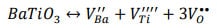
These intricacies collectively influence the reliability and lifetime of MLCCs 1–3. BaTiO3 emerges as the dominant dielectric material utilized in high-capacitance MLCCs, offering exceptional dielectric characteristics including high permittivity, low dielectric loss, and the capacity to adjust parameters across a broad temperature range. BaTiO3 has a perovskite crystal structure, where the Ba+2 ion occupies the twelve-fold coordinated A-site, the Ti+4 ion occupies the octahedrally coordinated B-site, and the O-2 ion occupies the anion site. The dominant stoichiometric defect reaction in BaTiO3 is the Schottky reaction, which can be expressed as:

Two distinct categories of BaTiO3-based MLCCs exist: precious metal electrode (PME) MLCCs and base metal electrode (BME) MLCCs. PME MLCCs are manufactured by sintering in an ambient air atmosphere, incorporating materials such as Ag, Pt, Pd, and/or Ag-Pd alloys as internal electrodes. Conversely, BME MLCCs require sintering under low oxygen partial pressures, employing Ni or Cu electrodes 4–6.
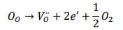
During the sintering process, which involves a reduction step for BaTiO3, it is crucial to prevent oxidation of the metal electrodes. To tackle this challenge, a re-oxidation anneal is performed at lower temperatures and partial pressure, to minimize oxygen vacancies while preserving the integrity of the metal electrodes 7–10. However, it should be noted that under such partial pressures and sintering temperatures, the Schottky reaction must be in equilibrium with the oxygen reduction equation, which is given by:

The concentration and mobility of oxygen vacancies, which are the primary mobile ionic defects in perovskite oxides, play a crucial role in the reliability of MLCCs. They are controlled by a complex interplay of partial Schottky reactions, compensation reactions, and reduction reactions 3,11. When an electric field is applied, positively charged oxygen vacancies migrate toward the cathode, passing through the ceramic grains. This electromigration causes the accumulation of oxygen vacancies at grain boundaries, resulting in the separation of stoichiometric charge carriers and the creation of a p-n junction across the dielectric layer and the blocking metal electrode causes depression of the Schottky barriers 2,3,12–15. This gradual process leads to an increase in leakage current under the electric field, thereby compromising insulation resistance and potentially paving the way for thermal or electrical breakdown.
To mitigate the electrical degradation caused by oxygen vacancies’ electromigration, various strategies can be implemented. Material engineering approaches involve optimizing sintering conditions, controlling oxygen partial pressures, and doping with rare earth elements (e.g., Dy, Y, and Ho) as well as metal cations like Mg or Mn. These approaches have significant promising results in limiting the formation and mobility of oxygen vacancies, thereby minimizing degradation phenomena 3,9,10,16,17. Furthermore, interface engineering approaches, such as grain boundary engineering and the utilization of interface layers, offer effective means to regulate the oxygen vacancies electromigration and minimize their adverse effects 3,18,19. The design of internal electrode interface plays a critical role in governing electron injection at the cathode, exerting a profound influence on the overall performance of BaTiO3-based MLCCs.
Impedance spectroscopy experiments on BME MLCCs have revealed distinctive components originating from various regions, including the core, shell, grain boundaries, and the ceramic/internal electrode interface. Analyzing the time-dependent behavior of leakage current reveals that tunneling through grain boundaries initially dominates, while the decline in resistance at the ceramic/internal electrode interface due to oxygen vacancy accumulation becomes increasingly pronounced as degradation progresses. Notably, it is observed that the influence of grain boundaries on oxygen vacancy electromigration appears to be less significant when compared to the substantial impact of resistance at the ceramic/internal electrode interface on degradation of the insulation resistance in BME MLCCs with thin active layers 7.
Internal electrode defects, including electrode discontinuity, roughness, and porosity, have a significant impact on the electrical reliability of MLCCs. Poor electrode quality in MLCCs leads to elevated leakage current density, shortened failure times, and reduced DC breakdown field strength 20–23. To enhance the overall reliability of MLCCs, a deliberate effort must be made to improve electrode quality. A comparative analysis of MLCCs sintered at different rates reveals that MLCCs subjected to fast fire rate of 3000 °C/h exhibit better electrode continuity. On the other hand, MLCCs fired at a slower rate of 150 °C/h exhibit inferior electrode morphology, resulting in significantly higher electric field enhancements and leakage current density 21. The presence of nonplanar and discontinuous electrodes leads to local field enhancements, and the relative morphologies of adjacent electrodes impact variations in the local dielectric thickness. Furthermore, as the dielectric layer thickness decreases, the influence of extrinsic defects like electrode porosity and roughness on electric field enhancement and leakage current density becomes more pronounced. Therefore, in the pursuit of targeted insulation resistance levels during miniaturization, simultaneous improvements in electrode morphology and continuity are of paramount importance.
Recent studies have also demonstrated that effectiveness of incorporating Cu or Sn into Ni internal electrodes to mitigate leakage current degradation in BME MLCCs 24,25. Suzuki et al. 26 investigated the influence of MLCC current leakage degradation on the distribution of electric fields within the internal electrodes and the degraded BaTiO3 layer using Kelvin probe force microscopy (KFM). Their findings support the observation that as the leakage current of MLCCs increases over time, the electric field concentration moves from the cathode to the anode side. These findings are aligned with those reported by Okamoto et al. 27, suggesting that the existence of the Ni-Sn internal electrode influences the concentration of electric field on the anode side. Remarkably, MLCCs with the Ni-Sn internal electrode on the anode side exhibit superior suppression of leakage current degradation compared to those positioned on the cathode side. A detailed analysis of the leakage current measurements from the degraded MLCCs revealed the presence of tunneling, Schottky, or Poole-Frenkel currents in the Ni and Ni-Sn internal electrodes, respectively. Furthermore, high-resolution transmission electron microscopy confirms the presence of a Sn-rich interface layer at the contact between BaTiO3 and the Ni-Sn internal electrode. This interface layer is critical in preventing leakage current deterioration in MLCCs 24,25.
In light of the discussed challenges, it is critical to ensure the consistent production of high-quality BME MLCCs and to conduct extensive quality assessment throughout the manufacturing process. This prospective article delves into the critical aspects of quality assessment and lifetime prediction of MLCCs, shedding light on recent research studies, existing challenges, and potential opportunities. It provides an extensive examination of the burn-in process, underscoring its role as a fundamental quality control procedure and emphasizing its profound impact on the lifetime and reliability of BME MLCCs. Additionally, this article advocates for the adoption of the thermally stimulated depolarization current (TSDC) technique as a promising and efficient approach for expeditious quality assessment during BME MLCC production. Furthermore, the article highlights the critical need for accurate and robust prediction of the failure time of MLCCs. It addresses the limitations of existing MLCC prediction models, particularly in determining the mean time to failure (MTTF). To overcome these limitations, a novel model is presented, one that seamlessly integrates the principles of physics with advanced machine learning techniques. This innovative model not only surpasses the performance of existing prediction models but also enables more precise predictions of failure times, effectively mitigating premature failures. Through the adoption of this physical-based machine learning approach, this article empowers the industry to elevate the reliability and performance of BME MLCCs in real-world applications. This ensures that these essential components consistently deliver optimal performance and reliability, meeting the stringent demands of modern electronics across diverse sectors.
Quality Assessment of Base Metal Electrode Multilayer Ceramic Capacitors
The ongoing development in understanding of materials, processing techniques, and properties of BME MLCCs has highlighted the critical importance of robust reliability analysis in long-term sensitive electronics. However, accurate reliability assessment remains a challenging, time-consuming, and unpredictable task. The hazard rate curve, which represents the instantaneous failure rate of components, plays an important role in the statistical reliability analysis of electronic components and products.

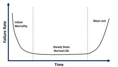
The bathtub curve is commonly recognized and used as the typical shape for hazard rate curves in electronic components and products. Nevertheless, it is crucial to acknowledge the inherent uncertainties associated with the actual shape of the hazard rate curve, as it cannot be definitively assigned a fixed form. These uncertainties arise from the complex nature of failure mechanisms and the intrinsic variability in the occurrence of failures over time. Further discussion on this topic will be presented in the subsequent section.
The bathtub curve, as presented in Figure 1, is divided into three sections: “infant mortality,” characterized by a decreasing failure rate at the initial stages; “random failures” with a constant failure rate during the expected life; and “wear-out failures,” exhibiting an increasing failure rate towards the end of the product’s lifetime 28.
While the general engineering goal for consumer products is to develop durable components with extended lifetime within economic constraints, it is critical to prevent infant mortality failures in high-reliability applications such as medical, aerospace, automotive, and military. To achieve this, it is crucial to implement a screening process that can identify components with a high probability of failure, reducing the occurrence of infant mortality and the probability of random failures during their normal lifetime without compromising overall reliability. The screening process for MLCCs involves subjecting the components to elevated temperatures and voltages for a specified duration, commonly known as a burn-in test 29–31.
In a recent study 32, the effect of the burn-in process, as prescribed by MIL-PRF-32535A 33, on the reliability of X7R BME MLCCs. According to the standard, the entire batch of capacitors must be tested at two or four times the rated voltage, at a temperature of 125 °C for 168 or 21 hours respectively. Utilizing the thermally stimulated depolarization current (TSDC) technique revealed that the burn-in test induces intragranular (ionic charge accumulation within individual grains) and transgranular (ionic transportation across each grain) oxygen vacancy electromigration, which does not relax after the screening process. This electromigration leads to a reduction in the protective effects of double Schottky barriers at grain boundaries and electrode interfaces 15. Furthermore, results from highly accelerated life tests (HALT) demonstrated that the required burn-in process not only fails to identify infant mortality failures effectively but also has a negative impact on the reliability of BME MLCCs by creating a weak population 32. Notably, the results indicate that intergranular electromigration of oxygen vacancies exerts a lesser impact on the lifetime and reliability of the components.
Previous studies have shown that the TSDC technique is a powerful tool for analyzing relaxation kinetics of polarizable defects and detecting various defect mechanisms in insulator materials, including changes in local defect dipole complexes, local electron trapping, and the development of ionic space charge, both intergranular and transgranular 3,32,34–39. Figure 2 provides a schematic representation of the typical TSDC experiment, where the sample is polarized at a specific temperature (Tp) under a constant electric field (Ep) for a duration, typically on the order of minutes. Subsequently, the sample is rapidly cooled to a lower temperature (T0), freezing the polarized defects. Depolarization occurs when the dielectric is short-circuited to T0, and the sample is heated, causing each polarization mechanism in a metastable state to depolarize and generate a current. The leakage current resulting from the depolarization of relaxing defects is measured using a PA meter under a constant heating rate 39.

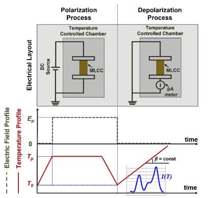
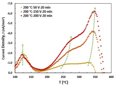
Moreover, the TSDC technique offers valuable insights into the physical origin of each relaxation peak, thereby enabling to assess the quality of MLCCs and their ability to resist the electromigration of oxygen vacancies. By analyzing the temperature dependence of the peak’s maximum (Tm) and its response to the electric field during constant rate heating, as demonstrated in Figure 3. When the relaxation current is related to trapped charges, the Tm tends to decrease. Conversely, if space charge is the underlying cause of the TSDC current, the Tm exhibits an increase 36,40. It is worth noting that the TSDC experiment usually requires minutes compared to the minimum 21 hours of the burn-in test. Consequently, the TSDC technique can serve as a sensitive and effective quality control process to assess the quality of MLCCs. By identifying suitable TSDC experiment conditions, MLCCs can be screened without inducing electromigration of oxygen vacancies, particularly across grain boundaries. Consequently, component quality can be assessed based on resistance to oxygen vacancy electromigration without jeopardizing component’s reliability.

Lifetime Prediction of Base Metal Electrode Multilayer Ceramic Capacitors
In industries that demand high reliability, it is crucial to minimize sudden failures due to safety concerns, the financial implications of failure, and the inability to repair components or devices. As a result, accurate prediction of the lifetime of electronic components holds significant importance. MLCCs warrant particular attention in this regard, as they serve as the primary passive components in hybrid circuits and are responsible for approximately 30 percent of failures observed in electronic systems.
HALT is a conventional method used to assess the degradation process and lifetime of MLCCs [61–66]. This stress test method is widely applicable for both development and quality control purposes. In HALT, MLCCs are subjected to significantly higher temperatures and voltages than those encountered in normal operating conditions to accelerate the testing process. The lifetime of MLCCs under normal operating conditions can be extrapolated from the failure times of components obtained through HALT. Two common models are commonly employed to estimate the MTTF of MLCCs: the Eyring model as an empirical model and the tipping point model as a physical-based model.
The Eyring model is expressed as:

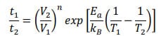
where t1 and t2 are the MTTFs measured at voltages V1 and V2 and at corresponding temperatures T1 and T2, respectively. The parameters n and Ea represent the electric-field acceleration factor, and activation energy of mobility governing the degradation process, respectively. While this empirical model provides adequate accuracy, the factor n is unphysical and varies depending on the test conditions 3,39,41. The determination of n values requires statistical analysis of a limited number of tests, and they typically remain constants that are independent of temperature and applied voltage in PME MLCCs.
However, n values are not constant in BME MLCCs, limiting lifetime predictions and necessitating extensive testing to determine the non-linearities of n. Care must be taken not to overstress an accelerated lifetime test to extremes that induce multimode failures that are not applicable to MLCCs under their operating conditions 39. To address the limitations of the Eyring model, the tipping point lifetime model was introduced. This physical model assumes the critical space charge density accumulation at the cathode interface and considers local fields 42. The lifetime of MLCCs in the tipping point model can be predicted using the following equation:

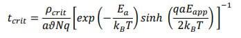
where tcrit and ρcrit represent the predicted lifetime and the critical space charge density at the cathode interface, respectively. a, , N, q, T, Ea, and Eapp are the characteristic hopping distance, characteristic jump frequency of the oxygen vacancy, oxygen vacancy concentration, oxygen vacancy charge, polarization temperature, the activation energy of the barrier height controlling diffusion, and applied electric field, respectively 42,43. Morita et al.41 modified the tipping point model by incorporating a depolarization field for low electrical fields.
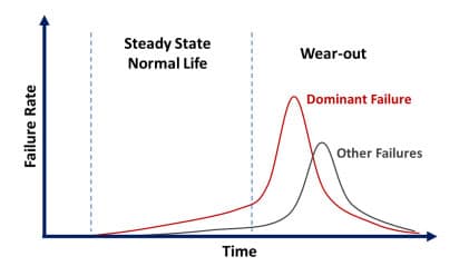
Our recent study 43 demonstrated that the tipping point model appears to be more systematic and predictable across all testing conditions compared to the Eyring model. However, it is worth emphasizing that both models heavily rely on extensive experimental data, which can be resource-intensive and time-consuming to acquire. Furthermore, the investigation into the factors contributing to the significant variation in error when predicting MTTF values using different models revealed noteworthy insights. The Eyring model’s sensitivity to the number of experimental data points used for fitting and the values of “n” and “Ea” played a substantial role in influencing its predictive accuracy. Specifically, the Eyring model’s performance deteriorated when extrapolating to conditions that the applied voltage was considerably different from the fitted data for BME MLCCs. In contrast, the variation in error observed in the tipping point model was primarily attributed to the dominant failure mechanism. An interesting finding was that when the most aggressive condition (highest voltage at each specific temperature) in the dataset was excluded, there was a notable reduction in the average error and standard deviation of MTTF predictions for the tipping point model. This implies that the tipping point model performs admirably as long as the dominant failure mechanism remains consistent and is the electromigration of oxygen vacancies. However, its accuracy diminishes when the dominant failure mechanism undergoes a shift, as illustrated in Figure 4.
It is important to acknowledge that while the bathtub curve is commonly used for hazard rate curves in electronic components, its actual shape varies due to uncertainties 28,29,44,45. Some researchers have proposed that the hazard rate curve exhibits a roller-coaster-like shape, reflecting latent failures and the involvement of multiple failure mechanisms in electronic components 46,47. Therefore, it is essential to have a comprehensive understanding of the hazard rate curve and its variability when conducting reliability analysis for BME MLCCs. By considering the complex nature of failure mechanisms, incorporating the roller-coaster behavior, and accounting for distinct failure rates, researchers and engineers can develop more accurate reliability models and strategies to ensure the long-term performance and durability of electronic components.

A more precise physical-based machine learning model has been recently developed to predict the MTTF of MLCCs under various temperature and voltage conditions. This model addresses the limitations of limited experimental data by expanding the dataset. Using a transfer learning framework, our model leverages the underlying physics from existing models to improve accuracy and stability across different test conditions, even with limited data. However, it is important to note that the size of our data is relatively small, and further research and validation are required to enhance the model’s performance and identify dominant failure mechanisms in different regimes. Furthermore, the current approach primarily focuses on voltage and temperature as the main features for predicting MLCC lifetime. Incorporating additional stress factors like mechanical stress and humidity could enhance the model’s predictive capabilities and provide a more comprehensive understanding of the reliability of MLCCs 43.
In the realm of MLCC reliability analysis, researchers frequently rely on the MTTF value as a key metric to estimate the lifetime of MLCCs under operating conditions, using models such as Eyring or tipping point models 42,49–56. However, it’s important to recognize that relying solely on MTTF presents limitations. MTTF alone does not encompass the entirety of the failure time data distribution, leading to inaccuracies in lifetime predictions and the possibility of unexpected failures. To achieve more precise lifetime predictions, it is imperative to account for the influence of voltage, temperature, and humidity on the complete failure time distribution. By incorporating the full spectrum of failure times, researchers can attain a more comprehensive grasp of MLCC lifetime, ultimately resulting in more reliable lifetime predictions. A crucial avenue of research in this field pertains to predicting the variance of the distribution as an additional component in comprehensive reliability analysis. This approach seeks to provide a more robust evaluation of MLCC lifetime, thus empowering better decision-making in terms of reliability and risk management.
Summary
Multilayer ceramic capacitors (MLCCs) are essential components of modern electrical devices. Preventing failures caused by infant mortality and sudden breakdowns that pose safety concerns in industries that demand high reliability is critical. therefore, it is critical to implement quality assessment procedures during MLCC production without jeopardizing the reliability of MLCCs.
Furthermore, accurate prediction of the lifetime of MLCCs is extremely valuable in preventing sudden failures. To address these challenges, the TSDC approach is proposed as a powerful technique for quickly assessing the quality of MLCCs. This approach provides useful insights into mobile defects and resistance of MLCC to oxygen vacancy electromigration, facilitating in determining the existence of potential flaws.
Furthermore, existing models for predicting the lifetime of MLCCs have limitations. A physical-based machine learning approach is highlighted to address these limitations. This approach not only improves the accuracy of existing lifetime prediction models but also serves as a foundation for developing new models capable of providing precise predictions regardless of the failure mechanisms involved.
Furthermore, incorporating relevant stress factors in these models allows for a comprehensive understanding of the failure time distribution. Ultimately, by leveraging the TSDC technique for quality assessment and employing a physical-based machine learning approach for accurate lifetime prediction, the electronic industry can improve the reliability of MLCCs, mitigate safety concerns, reduce financial losses, and facilitate more efficient repair processes.
Acknowledgements
This work is supported by the National Science Foundation, as part of the Center for Dielectrics and Piezoelectrics (CDP) under Grant Nos. IIP-1841453 and IIP-1841466”.
References
1 K. Hong, T.H. Lee, J.M. Suh, S.-H. Yoon, and H.W. Jang, “Perspectives and challenges in multilayer ceramic capacitors for next generation electronics,” J Mater Chem C Mater 7(32), 9782–9802 (2019).
2 H. Kishi, Y. Mizuno, and H. Chazono, “Base-metal electrode-multilayer ceramic capacitors: Past, present and future perspectives,” Japanese Journal of Applied Physics, Part 1: Regular Papers and Short Notes and Review Papers 42(1), 1–5 (2003).
3 C.A. Randall, and P. Yousefian, “Fundamentals and practical dielectric implications of stoichiometry and chemical design in a high-performance ferroelectric oxide: BaTiO3,” J Eur Ceram Soc 42(4), 1445–1473 (2022).
4 M.H. LaBranche, J.G. Pepin, and W. Borland, in ASM Thick Film Conference (1988).
5 J.G. Pepin, “Multilayer ceramic capacitor electrodes: powder technology and fired properties,” Journal of Materials Science: Materials in Electronics 2(1), 34–39 (1991).
6 W.R. Buessem, and T.I. Prokopowicz, “Electrode and materials problems in ceramic capacitors,” Ferroelectrics 10(1), 225–230 (1976).
7 H. Chazono, and H. Kishi, “dc-electrical degradation of the BT-based material for multilayer ceramic capacitor with Ni internal electrode: Impedance analysis and microstructure,” Japanese Journal of Applied Physics, Part 1: Regular Papers and Short Notes and Review Papers 40(9 B), 5624–5629 (2001).
8 M.R. Opitz, K. Albertsen, J.J. Beeson, D.F. Hennings, J.L. Routbort, and C.A. Randall, “Kinetic Process of Reoxidation of Base Metal Technology BaTiO 3 -Based Multilayer Capacitors,” Journal of the American Ceramic Society 86(11), 1879–1884 (2003).
9 G.Y. Yang, G.D. Lian, E.C. Dickey, C.A. Randall, D.E. Barber, P. Pinceloup, M.A. Henderson, R.A. Hill, J.J. Beeson, and D.J. Skamser, “Oxygen nonstoichiometry and dielectric evolution of BaTiO3. Part II—insulation resistance degradation under applied dc bias,” J Appl Phys 96(12), 7500–7508 (2004).
10 G.Y. Yang, E.C. Dickey, C.A. Randall, D.E. Barber, P. Pinceloup, M.A. Henderson, R.A. Hill, J.J. Beeson, and D.J. Skamser, “Oxygen nonstoichiometry and dielectric evolution of BaTiO3. Part I—improvement of insulation resistance with reoxidation,” J Appl Phys 96(12), 7492–7499 (2004).
11 S. Lee, C.A. Randall, and Z.K. Liu, “Comprehensive linkage of defect and phase equilibria through ferroelectric transition behavior in BaTiO3-based dielectrics: Part 1. Defect energies under ambient air conditions,” Journal of the American Ceramic Society 91(6), 1748–1752 (2008).
12 R. Waser, T. Baiatu, and K.-H. Hardtl, “dc Electrical Degradation of Perovskite-Type Titanates: I, Ceramics,” Journal of the American Ceramic Society 73(6), 1645–1653 (1990).
13 R.A. Maier, Dynamics of Oxygen Vacancies and Defect Complexes in the Pervskite Oxide Structure, The Pennsylvania State University, 2014.
14 R. Waser, T. Baiatu, and K.H. Hji, “Degradation of Dielectric Ceramics,” Materials Science and Engineering, A 109, 171–182 (1989).
15 T. Baiatu, R. Waser, and K.-H. Hardtl, “dc Electrical Degradation of Perovskite-Type Titanates: III, A Model of the Mechanism,” Journal of the American Ceramic Society 73(6), 1663–1673 (1990).
16 G.Y. Yang, E.C. Dickey, C.A. Randall, M.S. Randall, and L.A. Mann, “Modulated and ordered defect structures in electrically degraded Ni–BaTiO3 multilayer ceramic capacitors,” J Appl Phys 94(9), 5990–5996 (2003).
17 G. Yang, S. Lee, Z. Liu, C. Anthony, E. Dickey, Z. Liu, and C. Randall, “Effect of local oxygen activity on Ni–BaTiO3 interfacial reactions,” Acta Mater 54(13), 3513–3523 (2006).
18 K. Jiang, L. Zhang, B. Li, P. Li, S. Yu, R. Sun, Z. Fu, and X. Cao, “Importance of uniformity of grain size to reduce dc degradation and improve reliability of ultra-thin BaTiO3-based MLCCs,” Ceram Int 48(20), 30020–30030 (2022).
19 H. Gong, X. Wang, S. Zhang, H. Wen, and L. Li, “Grain size effect on electrical and reliability characteristics of modified fine-grained BaTiO3 ceramics for MLCCs,” J Eur Ceram Soc 34(7), 1733–1739 (2014).
20 M.M. Samantaray, A. Gurav, E.C. Dickey, and C.A. Randall, “Electrode Defects in Multilayer Capacitors Part I: Modeling the Effect of Electrode Roughness and Porosity on Electric Field Enhancement and Leakage Current,” Journal of the American Ceramic Society 95(1), 257–263 (2012).
21 M.M. Samantaray, K. Kaneda, W. Qu, E.C. Dickey, and C.A. Randall, “Effect of Firing Rates on Electrode Morphology and Electrical Properties of Multilayer Ceramic Capacitors,” Journal of the American Ceramic Society 95(3), 992–998 (2011).
22 A. V. Polotai, G.-Y. Yang, E.C. Dickey, and C.A. Randall, “Utilization of Multiple-Stage Sintering to Control Ni Electrode Continuity in Ultrathin Ni-BaTiO 3 Multilayer Capacitors,” Journal of the American Ceramic Society 90(12), 3811–3817 (2007).
23 A. V. Polotai, I. Fujii, D.P. Shay, G.-Y. Yang, E.C. Dickey, and C.A. Randall, “Effect of Heating Rates during Sintering on the Electrical Properties of Ultra-Thin NiBaTiO 3 Multilayer Ceramic Capacitors,” Journal of the American Ceramic Society 91(8), 2540–2544 (2008).
24 S. Suzuki, S. Yamaguchi, A. Doi, S. Abe, M. Matsuda, T. Nakamura, A. Ando, and H. Sano, “Effect of alloying Ni inner electrodes on the leakage current degradation of BaTiO3-based multilayer ceramic capacitors,” Appl Phys Lett 116(13), (2020).
25 S. Suzuki, S. Yamaguchi, A. Doi, A. Shiota, N. Iwaji, S. Abe, M. Matsuda, T. Nakamura, and H. Sano, “Suppressive effect of Ni-Sn internal electrode at the anode on the leakage current degradation of BaTiO3-based multilayer ceramic capacitors,” Appl Phys Lett 118(11), (2021).
26 K. Suzuki, T. Okamoto, H. Kondo, N. Tanaka, and A. Ando, “Insulation degradation behavior of multilayer ceramic capacitors clarified by Kelvin probe force microscopy under ultra-high vacuum,” J Appl Phys 113(6), 064103 (2013).
27 T. Okamoto, S. Kitagawa, N. Inoue, and A. Ando, “Electric field concentration in the vicinity of the interface between anode and degraded BaTiO3-based ceramics in multilayer ceramic capacitor,” Appl Phys Lett 98(7), 072905 (2011).
28 S.K. Kurtz, S. Levinson, and D. Shi, “Infant Mortality, Freaks, and Wear-Out: Application of Modern Semiconductor Reliability Methods to Ceramic Multilayer Capacitors,” Journal of the American Ceramic Society 72(12), 2223–2233 (1989).
29 J.A. van der Pol, E.R. Ooms, T. van’t Hof, and F.G. Kuper, in Annual Proceedings – Reliability Physics (Symposium) (Reno, Nevada, 1998), pp. 370–377.
30 M. Cooper, “Observations on Component Infant Mortality and Burn-In Effectiveness,” IEEE Transactions on Components and Packaging Technologies 31(4), 914–916 (2008).
31 W. Kuo, “Reliability Enhancement Through Optimal Burn-In,” IEEE Trans Reliab R-33(2), 145–156 (1984).
32 P. Yousefian, and C.A. Randall, “Determining the effect of burn-in process on reliability of X7R multilayer ceramic capacitors,” J Mater Sci 57(33), 15913–15918 (2022).
33 Department of Defense, “MIL-PRF-32535A,” (2017).
34 S.-H.H. Yoon, S.-H.H. Kim, and D.-Y.Y. Kim, “Correlation between i (current)-V (voltage) characteristics and thermally stimulated depolarization current of Mn-doped BaTiO3 multilayer ceramic capacitor,” J Appl Phys 114(7), 074102 (2013).
35 S.H. Yoon, J.S. Park, S.H. Kim, and D.Y. Kim, “Thermally stimulated depolarization current analysis for the dielectric aging of Mn and V-codoped BaTiO3 multi layer ceramic capacitor,” Appl Phys Lett 103(4), 042901 (2013).
36 P. Bräunlich, Thermally Stimulated Relaxation in Solids (Springer Berlin Heidelberg, Berlin, Heidelberg, Heidelberg, 1979).
37 A.K. Jonscher, “A new approach to thermally stimulated depolarization,” J Phys D Appl Phys 24(9), 1633–1636 (1991).
38 B. Akkopru‐Akgun, D.M. Marincel, K. Tsuji, T.J.M. Bayer, C.A. Randall, M.T. Lanagan, and S. Trolier‐McKinstry, “Thermally stimulated depolarization current measurements on degraded lead zirconate titanate films,” Journal of the American Ceramic Society 104(10), 5270–5280 (2021).
39 P. Yousefian, S. Rajpoot, and C.A. Randall, “Utilizing time domain electrical methods to monitor MLCCs’ degradation,” Appl Phys Lett 122(11), 112902 (2023).
40 A.K. Jonscher, in Universal Relaxation Law: A Sequel to Dielectric Relaxation in Solids (1996).
41 K. Morita, T. Shimura, S. Abe, and Y. Konishi, “Modified lifetime prediction for multilayer ceramic capacitors based on space charge evolution,” Jpn J Appl Phys 57(11S), 11UC03 (2018).
42 C.A. Randall, R. Maier, W. Qu, K. Kobayashi, K. Morita, Y. Mizuno, N. Inoue, and T. Oguni, “Improved reliability predictions in high permittivity dielectric oxide capacitors under high dc electric fields with oxygen vacancy induced electromigration,” J Appl Phys 113(1), 014101 (2013).
43 P. Yousefian, A. Sepehrinezhad, A.C.T. van Duin, and C.A. Randall, “Improved prediction for failure time of multilayer ceramic capacitors (MLCCs): A physics-based machine learning approach,” APL Machine Learning 1(3), 036107 (2023).
44 A. Peiravi, “Estimation of Expected Lifetime and Reliability During Burn in and Field Operation Using Markov Chain Monte Carlo Simulations,” Applied Sciences 4(6), 748–754 (2008).
45 A.T. English, and C.M. Melliar-Smith, “Reliability and Failure Mechanisms of Electronic Materials,” Annual Review of Materials Science 8(1), 459–495 (1978).
46 A. Gaonkar, R.B. Patil, S. Kyeong, D. Das, and M.G. Pecht, “An Assessment of Validity of the Bathtub Model Hazard Rate Trends in Electronics,” IEEE Access 9, 10282–10290 (2021).
47 K.L. Wong, and D.L. Lindstrom, in Annual Reliability and Maintainability Symposium (IEEE, 1988), pp. 356–363.
48 F. Wolff, D. Weyer, C. Papachristou, and S. Clay, “Design for reliability: Tradeoffs between lifetime and performance due to electromigration,” Microelectronics Reliability 117(January), 114025 (2021).
49 D. Liu, “Highly accelerated life stress testing (HALST) of base-metal electrode multilayer ceramic capacitors,” Proceedings – CARTS International 2013: The 33rd Symposium for Passive Electronic Components (2), 235–252 (2013).
50 A. Teverovsky, in 2017 IEEE International Reliability Physics Symposium (IRPS) (IEEE, 2017).
51 M.S. Randall, A.S. Gurav, D.J. Skamser, and J.J. Beeson, in CARTS Conference (Components Technology Institute, Inc., 2003), pp. 134–140.
52 A. Hernández-López, J. Aguilar-Garib, S. Guillemet-Fritsch, R. Nava-Quintero, P. Dufour, C. Tenailleau, B. Durand, and Z. Valdez-Nava, “Reliability of X7R Multilayer Ceramic Capacitors During High Accelerated Life Testing (HALT),” Materials 11(10), 1900 (2018).
53 J.-R. Yoon, K.-M. Lee, and S.-W. Lee, “Analysis the Reliability of Multilayer Ceramic Capacitor with inner Ni Electrode under highly Accelerated Life Test Conditions,” Transactions on Electrical and Electronic Materials 10(1), 5–8 (2009).
54 D. Liu, and M.J. Sampson, in CARTS USA (2011).
55 M. Nagayoshi, K. Matsubara, and N. Fujikawa, “Analyses of microstructure at degraded local area in Ni-multilayer ceramic capacitors under highly accelerated life test,” Jpn J Appl Phys 59(SP), SPPC01 (2020).
56 R. Confer, J. Canner, T. Trostle, and S. Kurtz, in 41st Electronic Components & Technology Conference (IEEE, 1991), pp. 320–322.

