

This paper shows some of the most recent examples of ceramic capacitor failures that ESA has detected, investigation on the potential cause and prevention.
The paper was presented by Adrià Escoda Marches and Joaquín Jiménez Carreira, European Space Agency (ESA), ESTEC, Noordwijk, The Netherlands at the 4th PCNS 10-14th September 2023, Sønderborg, Denmark as paper No. 3.4.
Abstract
Electrical, Electronic and Electro-mechanical (EEE) components used in space missions undergo rigorous testing to ensure their reliability and durability under demanding environmental conditions. Among them, passive components constitute a significant portion, accounting for approximately 80% of the parts used in a spacecraft. Typical ceramic chip capacitors space applications are filtering, bypass, de-coupling, temperature compensation, etc.
Capacitors are typically assembled on Printed Circuit Boards (PCBs) either through hand soldering or semiautomatic soldering processes. In the event of a failure within a PCBA (PCB Assembly), requiring the repair or rework of a component, the hand soldering assembly method is employed. Repair involves replacing the faulty component with a new one, while rework entails making additional modifications to the solder joint. However, such repair or rework operations can potentially subject the capacitors to an excessive thermal shock. In the case of type II ceramic chip capacitors, this leads to the development of cracks, creating a path through which electromigration processes may end up causing short-circuits. This is the reason why reworking processes on of type II ceramic capacitors was first forbidden by the ECSS-Q-ST-70-38C Rev1 (15 September 2017) and later by the ECSS-Q-ST-61C (8 April 2022). This paper shows some of the most recent examples of ceramic capacitor failures that ESA has detected.
Once the type II ceramic chip capacitors are accounted for, the European Space Agency (ESA) has initiated an investigation to assess whether submitting tantalum and flexible termination ceramic capacitors to rework or repair procedures should be forbidden or accepted. The objective is to gather comprehensive data through assembly and testing processes, providing insights into the behaviour and performance of these capacitors under such operations. This will eventually contribute to the development of guidelines for effective assembly practices in the European space industry.
References [1], [2]
CAPACITOR FAILURE LEADING TO IN ORBIT SATELLITE LOSS
Copernicus Sentinel 1B
Sentinel 1B C-band Synthetic Aperture Radar (C-SAR) payload malfunctioned and caused the spacecraft’s mission to end more than six years after its launch. It was discovered that the main problem was related to the 28V power regulated bus of the CAPS (C-SAR Antenna Power Supply). It was observed that the main and redundant 28V power regulators were both unexpectedly OFF. The CAPS is the unit which is part of the electrical power sub-system of the platform that provides power to SAR elements, including SAR electronics.
Detailed investigations were performed to understand the root cause of the CAPS anomaly, with the identification of 18 potential failures. The most probably root cause is related to a potential leakage of a ceramic capacitor. This capacitor had to be replaced as a result of a non-compliance detected during manufacturing and testing phase. For the repair process, the capacitor was assembled using direct wiring soldering process. At the time, neither reworking nor direct wiring on a ceramic chip capacitor were forbidden by the applicable product assurance requirements. Rework processes (or reprocessing) are no longer authorized following revision of the applicable ECSS standard in 2017 (ECSS-Q-ST-70-38C rev1). In addition, since 2019, the Memo ESA-TECQTM-MO-1143 also forbids direct wiring of type II ceramic chip capacitors and recommends the use of dedicated patch boards. This has been included in the recent ECSS-Q-ST-70-61C, issued on 8th April 2022.
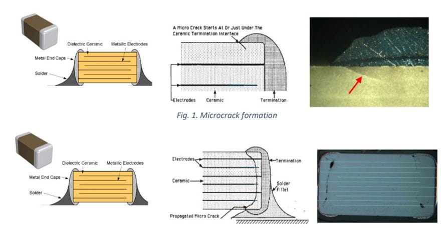
The failure mechanism consists of an on-chip heat distortion that was caused by direct wiring soldering, which resulted in the formation of a microcrack (Figure 1). The crack starts at the weakest point at the interface between the ceramic and the end of termination. After several thermal cycles, due to the CTE (Coefficient of Thermal Expansion) mismatch, the crack propagates (Figure 2).


SPACE UNIT FAILURE DURING ON-GROUND ACCEPTANCE TEST
During acceptance testing of a unit dedicated for space applications, some electrical anomalies were observed. A failure investigation was performed, and this established that the observed anomalies were related to a through hole multilayer ceramic capacitor. Specifically, to the part type CKR06 MIL-PRF-39014/02 (1µF, 50V) used in these units. Other units with this same part type of capacitor were analysed, and similar anomalies detected were related to this specific capacitor part type used.
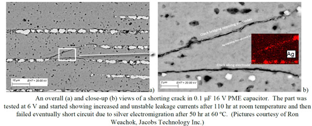
All the failed capacitors detected, seven in total, were submitted to thorough failure analysis investigations (electrical measurements, infrared thermography and microsections). This analysis confirmed that the failure mode of all failed capacitors was an electrical short-circuit. The failure is caused by cracks in the active area of the capacitors. These cracks, mainly originating from lead side and propagating to the active area, create a path through which the inner electrodes’ metal (mainly silver) starts to electromigrate. Eventually, opposite electrodes inside the active area of the capacitor end up electrically connected. This has a direct impact on the insulation resistance, drastically diminishing it with time – even after several years – and finally leading to an internal electrical short-circuit.
The root cause has been identified and related to the combination of several factors:
- the internal design and manufacturing process of the capacitor.
- improper assembly processes.
- mishandling during final integration of the unit’s board.
However, the most probable of them all is the CKR06 component’s internal design (a relatively large number of electrodes with relatively thin dielectric layers) and manufacturing processes (i.e., sintering, pressing, internal soldering, etc.). This makes the capacitor particularly susceptible and sensitive to cracks under thermal, mechanical and voltage stresses.
It is known that for low voltage failure mechanisms, multilayer ceramic capacitors with relatively thin dielectrics and/or relatively large voids, delamination, inclusions, microcracks, and other defects may develop low and unstable insulation resistances. These defects propagate to cracks, due to several stress factors (i.e., thermal, mechanical, or voltage). These defects have been observed in different areas of the capacitors.
It should be noted that inappropriate assembly process (i.e., excessive thermal stress) whether it is internal to the manufacturer or during the assembly of the capacitors, is considered as an extra stress factor that weakens the capacitors’ reliability.
According to these findings, ESA has considered to issue an ESA Alert concerning this CKR06 capacitor with the specific values of 1µF, 50V.
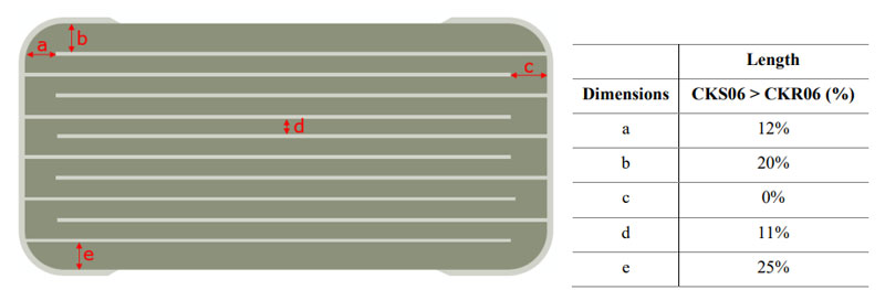
The ESA Alert recommends, as a preferred option for new procurement, to use the space grade alternative capacitor MIL-PRF-123/2 CKS06 1µF, 50V (part number M123A02BXB105KC) because of the part design and lot specific testing required by this high reliability specification.
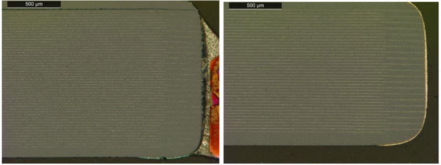
In general terms, the CKS06 internal design seems to be more reliable than the CKR06. The CKS06 type has 10 fewer internal electrodes than the CKR06 type. On top of this, the distance between internal electrodes, the distance between the active area and the external surface of the ceramic, and the distance between the end of one internal electrode and the termination, are all in average larger in CKS06 than in CKR06. All this contributes to a relatively lower probability of the appearance of cracks, due to a more robust internal design. Figures 4 and 5 show the differences between both capacitors.


RELIABILITY ASSESSMENT OF DIRECT WIRED TANTALUM CAPACITORS AND REWORKED FLEXIBLE TERMINATION CERAMIC CAPACITORS
The cracks described before have appeared in ceramic capacitors. Is it possible that similar issues might appear in Tantalum capacitors and Flexible termination Ceramic Capacitors? In order to answer this question, ESA is conducting an internal investigation in the framework of a YGT (Young Graduate Trainee) programme. The aim is to conduct reliability tests in order to collect data which might end up explicitly forbidding or not such rework processes for space applications. The findings of this research are foreseen to be the basis for an eventual update of the Standard ECSS-Q-ST-70-61C. Table 1 shows the list of capacitors that are ready to be procured for this investigation.
The selection of these parts was based on several key considerations in order to ensure a comprehensive and representative sampling of tantalum and flex termination ceramic capacitors. Firstly, the smallest and largest most used case sizes were included to encompass a variety of commonly encountered dimensions. This approach is also used for assembly verification processes.
Additionally, parts that can potentially be prone to cracks related to assembly processes were deliberately included. This deliberate selection allows for a thorough examination of the reliability and durability of the chosen parts, facilitating the identification of potential weaknesses in manufacturing or design processes.
Furthermore, the selection encompassed the broadest possible range of manufacturers. By including parts from various manufacturers, it becomes possible to assess performance and consistency across different sources. This approach provides valuable insights into potential variations in quality or reliability, enabling a robust assessment of the industry landscape.
By adhering to these criteria, our study ensures a diverse and representative selection of parts, covering different sizes, quality aspects, and manufacturers.
Some specific items in the list might be changed due to potential stock limitation or lead time issues. The quotation period plus the relatively long lead times of some of the components has caused a significant impact on the progress of this investigation, delaying it approximately 6 months.
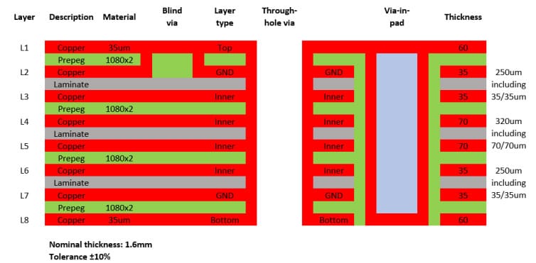
For the assembly of components, an 8-layer copper polyimide PCB has been designed. This is one of the most commonly used types of PCB for DC applications in space. The chosen PCB configuration was specifically tailored to meet the assembly requirements while accurately representing real-world scenarios. As part of the design, 12 fixations with a diameter of 4mm were strategically incorporated to securely position the PCB on the vibration platform during testing.
To simulate common via configurations, the PCB design incorporates a variety of via types. This includes blind vias, through-hole vias, and via-in-pad arrangements. The inclusion of via-in-pad structures represents a worst-case scenario due to the additional thermal dissipation during soldering, which requires a longer soldering time. The via is filled with a non-conductive resin that exhibits exceptionally low shrinkage, effectively covering the hole and providing structural reinforcement to the copper pad.

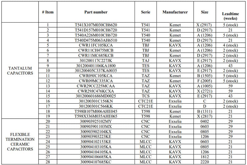
Figure 6 depicts the PCB stack-up, illustrating the arrangement of layers and the distribution of copper and polyimide materials within the design.
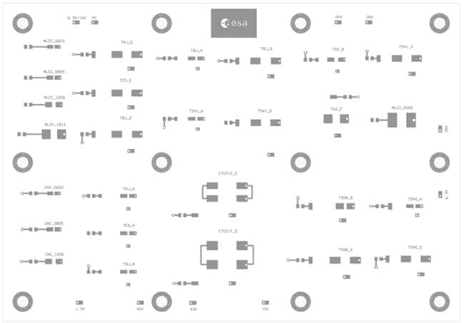
Additionally, Figure 7 illustrates the layout of the capacitors’ footprints, each one accompanied by a series 0805 resistor footprint for electrical purposes. This resistor ensures proper electrical protection to the circuit in case of a potential short circuit failure of one of the capacitors.
To enhance solder joint reliability, the top layer of the PCB will feature a SnPb finish. The quality of the PCB will adhere to the IPC Class 3 standard.
The assembly process of the procured capacitors will be performed by operators qualified to ECSS-Q-ST-70-61C. A total of six units will be mounted, which provides a representative sample size for drawing meaningful conclusions. The determination of the number of samples to be microsectioned is based on Memo ESA-TECQTM-MO-1143, which recommends an increased sample size for sensitive devices (e.g., ceramic capacitors type II). If required by the investigation, the number of capacitors evaluated can be extended, considering the availability of additional units already procured.
Two different approaches shall be followed according to the capacitor technology:
- Tantalum capacitors shall be assembled on the PCB with a direct wiring process. No rework shall be performed. Six units will be assembled where one of them shall be microsectioned just after the MIP 1 (Mandatory Inspection Point). The remaining five units will be submitted to the test campaign and only three of them will be microsectioned. The criteria for choosing the units to be microsectioned shall be based on what has been observed in the visual inspections and/or electrical measurements and/or x-ray inspection. If no difference is observed between them, then the samples shall be selected randomly.
- Flexible termination Ceramic Capacitors shall be assembled directly on the PCB and a rework shall be performed on the two terminals of each of the parts in accordance with ECSS-Q-ST-70-28C. Six units will be assembled where one of them shall be microsectioned just after the MIP 1. The criteria for choosing the unit to be microsectioned after the MIP 1 shall be based on what has been observed in the visual inspections and/or electrical measurements and/or x-ray inspection. If no difference is observed between them, the samples shall be selected randomly. The remaining five units will be submitted to the test campaign and all of them shall be microsectioned.

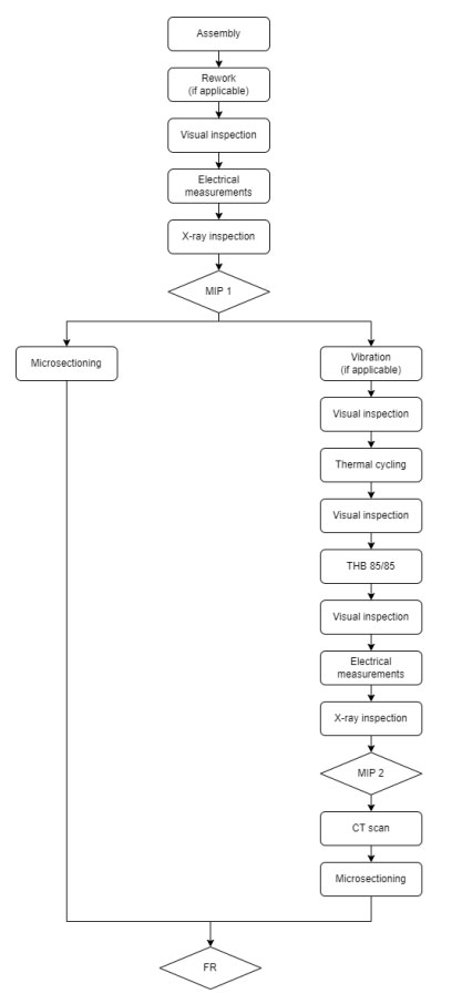
Figure 8 shows the test flow for this research. It is based on the verification assembly test flow specified in ECSS-Q-ST-70-61C with some modification to adapt better it to the evaluation of capacitors.
Some of the tests mentioned above in the flow test are explained in detail below.
- Vibration
In the case of vibration test is performed, it shall be in accordance with ECSS-Q-ST-70-61C. The levels shall be tested before starting the vibration campaign with an unpopulated PCB dedicated to check the vibration profile and shall not exceed 150 g r.m.s.
- Thermal cycling
Thermal cycling shall be performed in accordance with ECSS-Q-ST-70-61C. The number of cycles shall be 500 in total, performed in two stages: 200 thermal cycles + visual inspection + 300 thermal cycles. The temperature range shall be -55°C (-5°C, +0°C) up to +100°C (-0°C, +5°C) with a gradient of 10 °C/min and a dwell time of 15 min.
Before starting the thermal cycling, a 24/48-hour bake-out at 80°C shall be carried out to remove potential accumulated moisture from the tantalum and flexible termination ceramic capacitors. The thermal cycling shall always start from room temperature towards the higher temperature range. The last thermal cycle shall also end in the higher temperature range.
- Temperature Humidity Bias (THB) 85/85
The Temperature Humidity Bias (THB) test shall be performed at 85°C (±2°C) and 85% RH (±5%) for 1000 hours.
- X-ray inspection
2D X-ray inspection shall be performed after environmental testing on all assembled capacitors, to check the presence or absence of cracks.
- CT scan
CT scan shall be performed on the capacitors that have shown defects during the 2D X-ray inspections or anomalies during electrical measurements tests.
- Microsection
Microsectioning shall be performed in accordance with ECSS-Q-ST-70-61C. One populated PCB shall be microsectioned prior to the test campaign (after MIP 1) and the remaining after the test campaign (after MIP 2).
References [1], [2]
SUMMARY AND CONCLUSIONS
An overview of failed ceramic capacitors has been discussed: an example of a capacitor in-orbit failure that caused a spacecraft total loss has been provided, and details of a space unit failure during on-ground acceptance test have been presented. In both cases, the failures occurred on ceramic capacitors, being the first case related to rework processes.
That is why reworking processes on of type II ceramic capacitors is forbidden in ECSS-Q-ST-70-61C. In this context, ESA has initiated an investigation to assess rework and repair processes for tantalum and flexible termination ceramic capacitors.
The procurement of the components is relatively long due to current lead times and EEE components general shortage. Up to now, the test plan has been consolidated (fig.8) and the PCB has been designed, pending the completion of the procurement process. Once this is achieved, the assembly process will be performed, and the samples will be submitted to testing. Then the test data will be properly reviewed, analysed and consolidated. After that, a decision will be taken if the results can support an eventual update of the ECSS-Q-ST-70-61C Standard with the authorisation or prohibition of these processes for tantalum and flexible ceramic capacitors.
REFERENCES
[1] ESA-TECQTM-MO-1143 issue 2 (25 June 2019). “Subject: Devices that have shown anomalies during assembly on laminates or during verification programme as per ECSS-Q-ST-70-38”.
[2] ECSS-Q-ST-70-61C (8 April 2022) “High reliability assembly for surface mount and through hole connections”.
[3] Sentinel-1B in-flight anomaly summary report. https://sentinel.esa.int/documents/247904/4819394/Sentinel-1B+In-Flight+Anomaly+Summary+Report.pdf
[4] Teverovsky.A.; „Cracking Problems in Low-Voltage Chip Ceramic Capacitors”, NASA NEPP ASRC Federal Space and Defense, 2018. https://nepp.nasa.gov/files/29931/NEPP-BOK-2018- Teverovsky-Paper-NEPPWeb-BOK-Cracking-MLCC-TN65668.pdf

