This article explains shielding cabinet function, operation and effectiveness. The post is based on Würth Elektronik‘s “Reference Guide ABC of Shielding” that can be ordered from WE website here. Published under permission by Würth Elektronik.
Understanding the interactions between electronics and enclosures is crucial in today’s world. It’s essential to grasp how factors like shielding effectiveness, aperture sizes, enclosure material, peripheral cables, and grounding systems influence electromagnetic compatibility (EMC). These factors play a pivotal role in determining the quality of the product.
EMC shielding involves using shielding components to contain noisy parts of a device, preventing them from affecting other components or devices. It also protects sensitive areas of the device from external electromagnetic influences.
Effective shielding of a housing keeps electrostatic, magnetostatic, or electromagnetic fields away from or within a limited area. There are three main types of shielding: electrostatic or electrical shielding, magnetic shielding, and shielding of electromagnetic alternating fields. Electrostatic or electrical shielding involves surrounding the area to be shielded with a conductive wall. This prevents any field from penetrating the resulting cavity, ensuring that the interior is always field-free.
Magnetic shielding uses a soft magnetic material with a high permeability (typically µr > 1000) to surround the space to be shielded. The shielding effect increases with increasing µr and wall thickness. In the magnetostatic case, the shielding relies solely on the shunt effect of the magnetically well-conducting housing (magnetic circuit). In the case of alternating fields, the effect can be significantly enhanced by eddy current effects.
Shielding of electromagnetic alternating fields is similar to electrostatic shielding, but it also involves additional eddy current losses (Joule heat) and current displacement towards the surface (skin effect). The ideal case of a high-frequency shield is a completely closed metallic hollow sphere. In this case, the electric field component is completely reflected from the surface, effectively shielding it. However, the magnetic shielding is frequency-dependent as it penetrates the surface into the metal.
Completely shielded housings, devoid of seams and holes, can effectively safeguard the most delicate electronic components against electrostatic discharges. A metal housing enclosed on all sides (Faraday Cage) emerges as the optimal and most economical solution to:
- Contain a noise source, whether it’s an area or a specific component that generates electromagnetic interference (EMI).
- Protect sensitive components within a circuit.
In essence, Faraday Cages shield electromagnetic noise or safeguard sensitive components within a circuit. However, in practical applications, achieving this ideal is challenging due to the presence of holes, seams, and cable interfaces in housings, which can disrupt the shielding effect.
Shielding Cabinet Models
Shielding cabinets are metal structures that can be soldered to the PCB. They work by enclosing the source or victim of noise (EMI) inside a Faraday cage, redirecting all the noise and solving the issue. However, in practice, some design issues need to be considered. Cabinets mounted on PCBs will naturally have five sides, need to be connected to the PCB, may have slots, and need to be manufactured from some kind of metal.
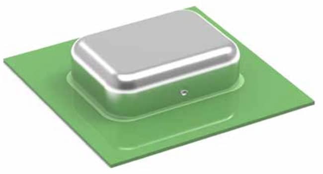
In order to use a shielding cabinet on a PCB, the cabinet must be connected to a ground plane to completely close the room and reach the damping behavior of the closed cabinet, the Faraday Cage Effect. The effectivity of a shielding cabinet is commonly expressed as shielding effectiveness (SE). Figure 1. shows such a shielding cabinet with its connections to the PCB ground.
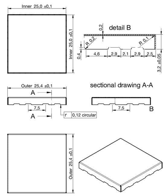
Figure 2. shows a technical drawing of a shielding cabinet – example of WE-SHC.
According to their structure there are two types of shielding cabinets:
Standard Shielding Cabinets
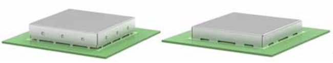
These parts are produced by a generic stamp and bending process. They have small openings at the corners due to the production method but they are very effective for general applications. This type of shielding cabinet is shown in Figure 1. above.
Seamless Shielding Cabinets
The production method for these parts involves deep drawing, which eliminates openings on the edges or sides. This enhances the shielding effectiveness, particularly for higher frequencies and emerging challenges like 5G and IoT. As depicted in Figure 2., these types of cabinets are fully soldered to the PCB, reducing the number of openings and further improving shielding. The seamless cabinet is the ideal choice for high and very high frequencies.
Characterization of Shielding Cabinets
Mounting Technology
Shielding cabinets typically come in two main technologies: Through-Hole Technology (THT) and Surface-Mount Technology (SMT). The shielding effectiveness of a cabinet is directly proportional to the highest frequency it needs to shield and the distance between the solder points (gaps or slots). Therefore, for shielding high frequencies (>1 GHz), the SMT variant may be more suitable because the distance or gap between the cabinet and the fixing point will be shorter compared to the THT variant. Shielding cabinets are designed with pins or fixing points, leaving slots between them that allow the feed-through of traces from internal components.
Setup
There are two main types of shielding cabinets according to their setup. Both standard and seamless shielding cabinets can be divided into:
One-piece shielding cabinet
The one-piece cabinet shown in Figure 1. is composed of only one piece and it is directly soldered to the PCB. One-piece cabinets are more effective in terms of shielding effectiveness as they present less openings.
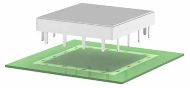
Two-piece shielding cabinet
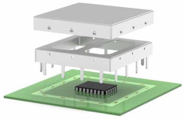
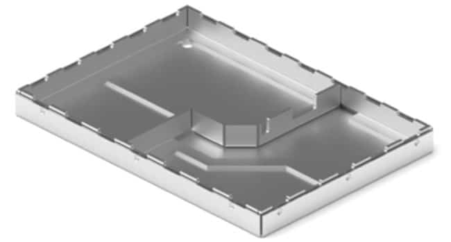
The two-piece cabinet shown in Figure 4. consists of a frame and a cover. In this case, the frame is soldered to the PCB simultaneously with the inner components, and the cover can be inserted and clipped afterward. The primary advantage of this type is that visual inspection and verification of the inner components can be conducted after soldering.
The frame of a two-piece shielding cabinet is designed with a metallic cross joining the sides to provide stability and a designated point for pick & place machines. Typically, the frame is automatically placed during the pick & place process, while the cover is manually placed after the soldering process. To secure the cover, a lock system on the sides fixes the frame, ensuring low and stable contact resistance.
Raw material
The material used in shielding cabinets significantly impacts operating frequencies, oxidation resistance, and customization options. Steel with a tin coating is the most commonly used raw material for shielding enclosures due to its ease of soldering compared to other materials like brass or nickel silver. It’s also easy to machine and performs well in low and medium frequencies below approximately 2 MHz. Above this frequency, the material’s conductivity is crucial, as 99% of the wave is reflected.
For applications requiring higher corrosion resistance, such as humid environments, nickel silver (CuNi18Zn20) is an excellent choice. Despite its name, it doesn’t contain silver. However, it’s named after its color and historical significance. The alloy’s composition provides exceptional corrosion resistance while facilitating easy soldering without tin whisker issues. In essence, nickel silver is stronger and more durable than silver.
The two materials mentioned above are the most commonly used, although there are other options for high frequency shielding such as tin-plated copper, copper beryllium and phosphor bronze. Brass-based materials are also widely used for small-sized stamped cabinets. For ultra-lightweight applications where every gram counts, tin-plated aluminum can be used. It not only provides high thermal conductivity but also an acceptable shielding effectiveness. Another option is the use of composite materials or plastic shielding cabinets with metal coatings, but note that this option is not very effective in terms of shielding effectiveness.
Coplanarity
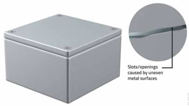
Coplanarity is a crucial characteristic of how housing components are assembled. Good coplanarity reduces the contact resistance between components, decreases the size of openings, and consequently enhances the shielding effectiveness of the housing, improving its immunity to electrostatic discharge.
However, using the incorrect stencil or employing a cabinet with poor coplanarity can lead to solderability issues, which in turn decrease both the mechanical stability and the shielding effectiveness of the shielding cabinets. Therefore, selecting the appropriate stencil is paramount to ensure coplanarity and achieve optimal performance from the soldered shielding cabinet. As illustrated in Figure 5., coplanarity is high when the gap around the entire package is uniform and as small as possible.
Shielding effectiveness
As stated in the introduction, any kind of aperture will have an effect on the shielding effectiveness, the more and the bigger the apertures the less effective the shielding will be. This is the main reason of the existence of seamless shielding cabinets.
As soon as we start working with frequencies over 1 GHz we see that the effectiveness of the conventional shielding cabinets starts to decrease. It is possible to calculate the critical frequencies with the following equation by applying it to the corners, open slots between pins and (if there are) ventilation openings of a shielding cabinet. More information about openings in housings are given in article Electromagnetic Emissions Leakage in Enclosures.
f = C / λ
Where,
- f: Frequency in Hz
- C: Speed of light in m/s (299,792,458 m/s)
- λ: Wavelength in m
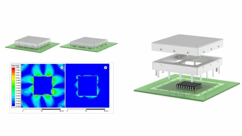
Figure 6. shows simulation models of a conventional and a seamless shielding cabinet. An excited microstrip line, with a sinusoidal signal of 1 VRMS at 8 GHz, is placed on the interior to generate a known magnetic field.
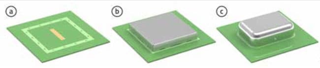
Figure 7a. shows the leakage through the opening areas between soldering pins, of a conentional shielding cabinet with a magnetic field at 8 GHz. As can be seen in Figure 7b., the seamless shielding cabinet, is able to improve the shielding effectiveness significantly.
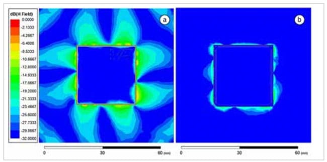
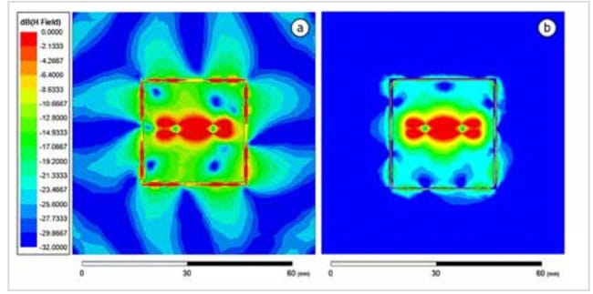
Figure 8. illustrates the evolution of the field within the shielded cabinets and its subsequent escape through the pins of conventional cabinets and the fully soldered, seamless version. The latter exhibits a superior ability to contain the field from a qualitative perspective.
The magnetic field level at the critical points (corners) of a conventional cabinet is approximately 30 dB higher compared to that of a seamless shielding cabinet, as illustrated in Figure 9.
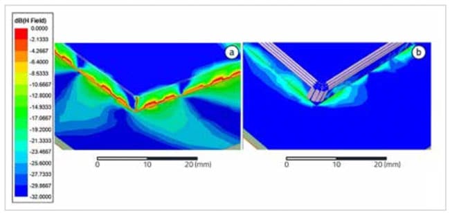
Figure 9. illustrates the observed magnetic field from an external perspective. On the other hand, the side view enables an examination of the penetrating field through the corners and sides. The seamless version proves particularly effective when dealing with frequencies exceeding 1 GHz. Furthermore, the complete soldering of the cabinet enhances the contact points with the ground plane, thereby reducing the openings on the footprint. Consequently, this significantly improves the overall shielding effectiveness.
Thermal Management
On the other hand, ventilation holes are often necessary in cabinets to provide more effective thermal management of the shielded parts. A shielding cabinet with ventilation holes is illustrated in Figure 10.
Depending on the application, heat transfer from the interior of the cabinet to the exterior may be required. If insufficient heat transfer capabilities are present, the shielded component could overheat, leading to accelerated aging and failure. In such cases, it is common to use cabinets with holes to enhance convection cooling of the assembly.
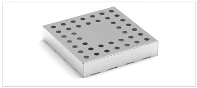
The number and size of the holes play a crucial role in determining the maximum frequency that can be attenuated or shielded, as well as the effectiveness of this attenuation. Since a shielding cabinet essentially functions as a Faraday Cage, the more openings it has, the less effective it becomes from an electromagnetic compatibility perspective. This relationship is illustrated in Table 1.
| Number of holes | Shielding reduction (dB) |
| 2 | 3 |
| 4 | 6 |
| 6 | 8 |
| 8 | 9 |
| 10 | 10 |
| 20 | 13 |
| 30 | 15 |
| 40 | 16 |
| 50 | 17 |
| 100 | 20 |
As mentioned in article Electromagnetic Emissions Leakage in Enclosures, the radiation of a magnetic field through holes also depends on the distance between the source and the holes, the field polarization and the wavelength. The shielding reduction caused by slots and openings in cabinets is calculated with:
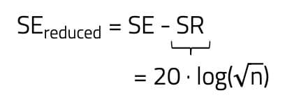
Where,
- SR: Shielding reduction in dB
- SE: Shielding effectiveness in dB
- N: Number of slots
The size of the holes or slots becomes critical when sizes between λ/20 and λ/2:
| Frequency (MHz) | Maximum length (cm) |
| 30 | 46 |
| 50 | 30 |
| 100 | 15 |
| 300 | 5 |
| 500 | 3 |
| 1000 | 1.5 |
| 3000 | 0.2 |
Another option to enhance the thermal management of the assembly is to insert a thermal gap filler within the cabinet to fill the vacant space between the shielded component(s) and the cabinet, as air is an inefficient thermally conductive material. In contrast, these materials possess high thermal conductivity, enabling them to transfer heat from the bottom to the top very efficiently.
Customization of Shielding Cabinets
For certain applications, the standard shielding cabinets available in the market may not be sufficient, necessitating a specialized solution. Shielding cabinets can be customized to meet specific requirements based on the following factors:
- Slot and openings: These can be added for additional entrance/exit points or improved thermal management.
- Shape: The length, height, and width of the shielding cabinet can be tailored to fit the desired space.
- Compartmentation: Internal compartment solutions are more cost-effective than using multiple cabinets. Additionally, compartment openings can be incorporated for antenna positioning or internal components that should not be enclosed.
- Markings: Logos, serial numbers, build numbers, and other relevant information can be printed on the top of shielding cabinets for identification purposes.
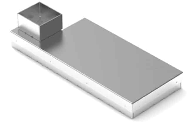
Some examples of customization possibilities are shown in Figure 11. and Figure 12.
Additional Options for Shielding Cabinets
Shielding cabinet clips
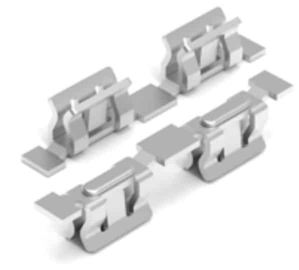
These clips enable pluggable one-piece type and prototyping solutions. The small clips shown in Figure 13. are designed to be soldered directly onto the PCB and serve as a mounting point for the cabinets.
As a recommendation, for shielding cabinets with a side length less than 20 mm, the clips should be positioned in the center of each side.
For cabinets with a side length exceeding 20 mm, the clips should be placed on the edges. It’s crucial to ensure that the clips are soldered to the ground plane or return plane. Additionally, it’s important to consider the number and placement of clips required.
The more clips used, the better the connection points to the ground plane, and the fewer openings, the more effective the shielding becomes.
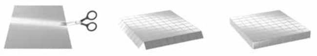
Do it yourself cabinet
An alternative option for the prototyping stages of a project is the DIY shielding cabinet depicted in Figure 14. These are pre-scored metallic sheets (typically nickel silver) that can be easily cut and folded. This facilitates testing various solutions, even during the redesign of the electronic circuitry.
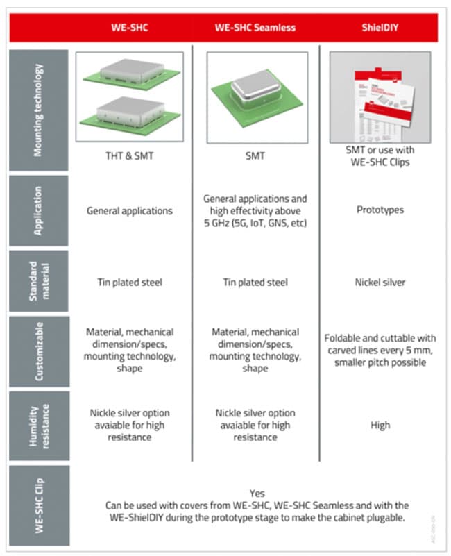
Overview of Different Shielding Cabinets
Depending on the design stage, there are several suitable shielding cabinet options. The overview in Figure 15. provides a guide on how to select a shielding cabinet type based on the current design stage and capabilities.