
source: EDN article
In Part 1, we have reviewed solar cell performance, how to select and size the supercapacitor, requirements of supercapacitor charging circuits and charging IC characteristics. We will now use two case studies to illustrate these properties in detail.
Case Study 1 – Using a small solar cell indoors at low light, 100 lux, to power a Bluetooth low energy sensor using CAP-XX GA109
In this case we used a low power BLE sensor operating in low indoor light down to 100 lux. The sensor only operates when there is light, so the supercapacitor only needs to support data acquisition and transmission.
We used a Sensor Puck BLE sensor reporting temperature, relative humidity and light level to a phone app every second. The sensor max-min supply voltage range is 3.0V to 2.0V, therefore we will use a single cell supercapacitor with a maximum cell voltage = 2.5V. Figure 9 shows the current and voltage waveform while the sensor is acquiring and transmitting data. The peak current is ~22mA for 1ms duration, while the sustained burst has an average current of 4.5mA over 12ms, with a small peak of 5mA at the end of the pulse. Figure 5 shows this current is >> solar cell current of 260µA at the peak power point. In this case, we have chosen a CAP-XX GA109 supercapacitor, 180mF, 40mΩ. This is a small prismatic supercapacitor that enables a slender attractive industrial design. The test setup is shown in Figure 8.
The voltage drop at the end of the 22mA peak = 22mA x 1ms/180mF + 22mA x 40mΩ = 1mV
The voltage drop at the end of the 12ms, 4.5mA pulse with a 5mA peak at the end = 4.5mA x 120ms/180mF + 5mA x 20mΩ = 5mV. Figure 5 shows a voltage drop over the pulse of ~6mV which confirms the calculation. This is a negligible drop and enables the GA109 to support the Sensor Puck for multiple transmissions. Figure 9 also shows the Sensor Puck transmitting every second, and the supercapacitor voltage decaying slightly between transmissions. This is because the solar cell charge power < average power drawn by the sensor transmitting once per second.


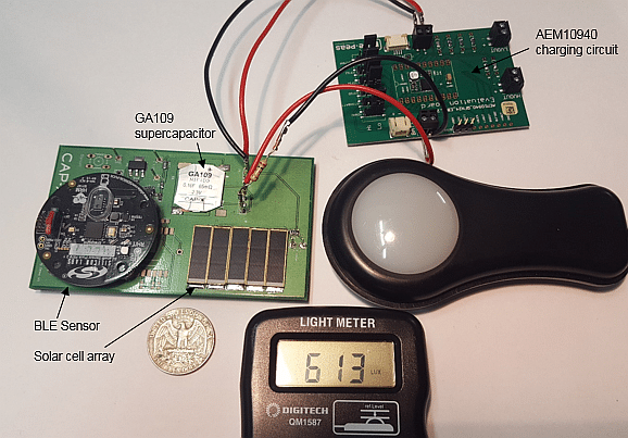
Figure 8: Lab test setup with small solar cell
![]()
Figure 9: BLE sensor current during transmission
To make the system sustainable, the load power must be limited to the solar cell charging power. We have done this, referring to Figure 10, by including a comparator with hysteresis, U1, controlling a FET, M1, between the supercapacitor and sensor. When the supercapacitor reaches 2.4V M1 turns ON, enabling the sensor to run. When the supercapacitor discharges to 2.2V M1 turns OFF disconnecting the sensor and enabling the supercapacitor to be re-charged to 2.4V. Fig 10 shows our charging circuit, with 5 solar cell strings in parallel supplying the AEM10940 charging the supercapacitor.

Now that since we are disconnecting the power supply to the BLE sensor to regulate the average load power, when the sensor is turned on it will re-initialize. This draws an average of 12mA for 2.1secs. The GA109 voltage drop during initialization = 2.1s x 10mA/180mF + 12mA x 40mΩ = 117mV. Our 200mV hysteresis allows the GA109 to support sensor initialization plus several transmit bursts.
Figure 11 shows the effectiveness of this circuit charging the supercapacitor at 100 lux and then maintaining transmission. 100 lux is very dim light, insufficient to read by, illustrating that a solar cell solution is feasible even in such poor light.
Figure 11: GA109 supercapacitor charged with 100 lux light power
Figure 11 shows that in such low light it took 45hrs to charge the GA109 supercapacitor from 0V and then 2.6hrs to re-charge after it has supplied a transmission burst from the sensor. Designers can overcome the slow initial charge time by pre-charging the supercapacitor at installation. Figure 12 shows how effectively the system works in reasonable light. 650 lux is the light level in a well-lit office, supermarket or factory floor. Figure 3 shows that at 650 lux, solar cell power is just over 0.4mW. It only takes 31 mins to charge the GA109 from 0V and 2 mins 5s to re-charge the supercapacitor after supplying a transmission burst. The 2.9s duration for the sensor on time indicates the GA109 is supporting initialization followed by a transmit burst.
Figure 12: GA109 supercapacitor charged with 100 lux light power
This case study has shown how a small solar cell and efficient charging IC can charge a supercapacitor to support low power sensor acquisition and transmission. The e-peas AM10940 is an efficient IC that can charge the supercapacitor even when the solar cell provides only 150µW, and does so much more effectively with an increase in solar cell power to a little over 400µW. The GA109 is a small, thin supercapacitor, with sufficient C and low ESR to enable construction of an unobtrusive sensor suitable for wearables or indoors where cosmetic appearance is important.
Case Study 2 – Using a larger supercapacitor to support solar cell applications during a dark period
In this case study we will use the same solar cell used in case 1, but with outdoor lighting on a sunny day. This will be used to support an SMS lasting 2 seconds every ½ hour. The SMS burst is transmitted using GPRS class 10, with 2A 1.1ms pulses at 25% duty cycle. The max-min voltage in this application 3.8V – 3.0V and the supercapacitor should support transmission with no light for 12 hours. CAP-XX has recently released a cost-effective range of cylindrical cells from 1 – 400F for applications that require greater C but are not constrained to a thin prismatic form factor by the industrial design.
Figure 4 shows that in sunshine, at 83,000 lux, the solar cell delivers 62mW peak power at 1.26V, 49mA. The LTC3105 selected for this case is ~80% efficient at this application, hence supercapacitor charging current = 49mA x 1.26V/3.8V x 80% = 13mA.
The average load current in this application = 2A x 25% x 2s/1800s = 0.56mA
This means that during the day, the application is self-sustaining with average current < average supercapacitor charging current. Even on a cloudy day, charging current » 4mA, so the application is sustainable.
Sizing the supercapacitor in this application requires an iteration between C and ESR, leakage current and self-discharge.
Since the load is high current and operates up to 3.8V, a dual cell supercapacitor is selected. It can directly supply the peak 2A load current.
To support the application without light for 12hrs, C > 0.56mA x 12 x 3600s/(3.8V-3.0V) = 30.2F (3)
Select a pair of GY12R718060M107R 100F cells in series. Their ESR is 15mΩ, so 30mΩ for the 2 cells in series. The voltage drop due to the 2A pulse x 30mΩ = 60mV, so the denominator in equation (3) should be (3.8V – 3.06V), which slightly increases the required C to > 32.7F, so the selected supercapacitor still meets the requirement.
The leakage current for the 100F cells in series is shown in Figure 13. Since there are 2 cells in series, they require a balancing circuit to ensure their voltages are equally distributed. The simplest circuit is a pair of resistors but this will draw too much current and discharge the supercapacitors over the 12hr dark period, so we have used an active balance circuit, described later, that only draws ~3µA. The leakage current shown in Figure 13 includes the current drawn by the active balance circuit.
Figure 13: Dual GY12R718060M107R 100F supercapacitor cells in series with active balance
This leakage current » 130µA << supercapacitor charge current of 13mA in sunshine or 4mA when overcast. Since the supercapacitor must support the application for an extended period without charging, we must consider its self-discharge characteristic, shown in Figure 14 which we extended to 70hrs. Over 12hrs the supercapacitor module has discharged from 3.797V to 3.776V or 21mV and over 70hrs to 3.693V or 104mV.
Figure 14: Self discharge for CAP-XX 50F module with active balance
A common mistake is to model self-discharge as a constant current discharge at the leakage current, or to model the leakage current as a parallel resistor to the supercapacitor, in this case 3.8V/130µA = 29.2KΩ and model self discharge as V = Vinit.e(-t/RC) where in this case R = 29.2KΩ and C = 50F. In Figure 14, we demonstrate that these two models significantly over-estimate self-discharge. Self-discharge is a diffusion process, with ions migrating from the pores in the carbon electrode. Diffusion is proportional to sqrt(time). Our empirically determined estimate for the 50F module’s self-discharge is given in Figure 14. If supercapacitor self-discharge is important in your application, we recommend you empirically determine this with a sample of parts. Self-discharge is also temperature dependent.
Supercapacitor C must now satisfy C > 0.56mA x 12 x 3600/(3.8V-3.0V – 0.06V – 0.021V) where 0.06V was the ILOAD x ESR voltage drop and 0.021V = self-discharge loss. Min C must now be > 33.6oF.
The setup is shown in Fig 15.
Fig 16: Charging circuit for 50F module – outdoors in sunlightThis circuit uses an active balance circuit to minimize leakage current and self-discharge. IC2 is a voltage follower with the reference set as the midpoint of the supercapacitor terminal by R3 and R5. The MAX4470 only draws 750nA quiescent current and can deliver 11mA output current. When the system is in balance it will only draw 3.8V/2MΩ + 750nA + difference in leakage current between the 2 cells, typically a few µA in total.
Figure 17 shows the supercapacitor charging from 0V in sunlight. The solar cell delivers ~13mA charge current to the supercapacitor when the LTC3105 is in the cold start region, then increases to over 20mA when the charging IC starts acting as a boost and tapers off to 13mA as the supercapacitor reaches 3.8V.
Figure 17: Charging the 50F module from 0V in sunlight
Even though the supercapacitor is 50oF, the small solar cell in sunlight manages to charge it in 3½ hours.
Figure 18 shows the supercapacitor module supporting 2 second GPRS bursts every ½ hour. The inset shows the GPRS pulse train in detail with 1.15ms 2A pulses every 4.6ms. Points to note in Figure 18 are:
– The very small voltage dip discernible in Vcap when the GPRS burst occurs
– How the LTC3105 draws more current from the solar cell after the pulse burst to charge the supercapacitor
– When the supercapacitor is fully charged the LTC3105 turns off and the solar cell current, Isolar = 0. As the supercapacitor slowly discharges through the ½ hour between pulse bursts, the LTC3105 hysteric function turns the charger on until the supercapacitor is fully charged again.
Figure 18: Charging the 50F module from 0V in sunlight
Figure 19: Self-discharge while supporting the SMS messages over 12 hours
Fig 19 shows the 50F module supporting the GPRS bursts every ½ hour over a 12hrs period. Vsupercap ends 3V at the end of 12hrs, so the requirement is met, but with no headroom. This final voltage is a little lower than expected. Theory predicts the final voltage for a 50oF, 30mOhm module = 3.8V – (0.56mA (average load current) x 12 x 3600s/50oF + 2A (peak current).30mΩ (ESR) + 21mV (self-discharge) = 3.23V
This case study has shown how to use a large supercapacitor with a low-power solar cell energy source to support a high-power application, even in periods of no light. The supercapacitor has the following advantages over a battery in this application: physical charge storage, so “unlimited” cycle life, low ESR able to deliver high power and excellent low temperature performance for outdoor applications in winter. Following the experimental result shown in Fig 19, there needs to be further work to identify the cause of the greater-than-expected discharge and possibly use larger cells.
Recap
This article has reviewed: 1) how to characterize a solar cell for your application, 2) the properties of supercapacitors that make them an ideal power buffer, enabling a low power solar cell to support an application with high power bursts and average power < charging power the solar cell delivers, 3) how to size the supercapacitor required, taking into account both the energy used by the load and the peak current, 4) the characteristics required of supercapacitor charging circuits, 5) the criteria for selecting a charging IC and 6) two case studies demonstrating these principles.

