
source: EDN power management design center application notes
Why supercapacitors?
Depending on the light level, whether indoors or out, small solar cells may deliver sub mW to 10’s of mW. The peak application power may range from ~50mW for Bluetooth to ~7W for cellular transmission. So the problem becomes how to power wireless transmission, which requires higher power, from a low-power source. Supercapacitors solve this problem playing the roles of temporary energy storage and power delivery.This article will examine how to use supercapacitors with small solar cells with two case studies:
- For relatively low power applications which only operate when there is indoor light, providing sub mW power and transmitting with BLE. The supercapacitor need only be sized for the energy and power to support the peak load burst.
- An outdoor solar cell for higher power applications which must run when there is no light, such as overnight and reports by SMS using GPRS. In this case the supercapacitor is sized for energy storage over the dark period as well as for the peak load.
Small, thin prismatic supercapacitors are ideal for the first case, particularly for small, space-constrained sensors where form-factor is important such as in wearables. Larger cylindrical cans up to 400F are best for the second case. I will use CAP-XX supercapacitors to demonstrate both cases.
Supercapacitors are an ideal power buffer
Prior to low-impedance supercapacitors, designers needed to size the entire power supply system for the load’s peak power. As an example, assume a remote location is reporting its status once per hour using an SMS that takes three seconds to transmit on a GPRS cellular network. The peak output power is ~7W. For GPRS class 8 (single slot transmission), the average power = 7/8W and over three seconds ~2.6J of energy. The only solution without a supercapacitor is to have a solar cell that can deliver 7/8W or to trickle-charge a battery that can deliver this power, possibly with the support of a tantalum or electrolytic capacitor for the 0.577ms 7W transmission peaks.
The supercapacitor’s high energy storage and high power delivery make it ideal to buffer a high-power load from a low-power energy-harvesting source, as shown in Figure 1. The source sees the average load, which with appropriate interface electronics, will be a low-power constant load set at the maximum power point. The load sees a low-impedance source that can deliver the power needed for the duration of the high-power event. The only constraint is that the average power from the solar cell > average load power = load power x duty cycle /efficiency of supercapacitor charger. The supercapacitor charger is also sized for the average load power, not the peak, so a smaller, lower-cost charger can be used.


Figure 1: Supercapacitor as a power buffer
Supercapacitors use physical charge storage rather than electrochemical so have “unlimited” cycle life. They also have a wide operating temperature range with Equivalent Series Resistance (ESR) at -40°C approximately twice room temperature ESR, so can be used in outdoor applications such as perimeter security in colder climates such as North America and Europe.
The physical charge storage and low ESR supercapacitors mean they have excellent round trip charge/discharge efficiency, another beneficial attribute for a power buffer. The losses in charging / discharging a supercapacitor are the I2 ESR losses.

Where t is the time to charge the supercapacitor from V1 to V2 at current I

A worst case would be a supercapacitor supporting GPRS transmission, discharging from 3.8V to 3.2V supplying 2A peak current. If the supercapacitor ESR = 100mΩ, then discharging efficiency = 95%. If the solar cell charges the supercapacitor at 50mA, which is the peak power current in Figure 4, for the second case study, then charging efficiency = 99.9%.
Supercapacitors are also very simple to charge, only needing charge current with over-voltage protection rather than a constant voltage constant current regime.
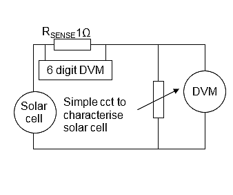
Characterize the solar cell Solar cell datasheets typically specify a V-I characteristic and peak power at 1 sun: 1KW/m2 or 100,000 lux. It can be difficult to estimate the power delivered in your typical lighting conditions so it is best to characterize the solar cell in those conditions. This is easily done with the circuit of Figure 2.

Figure 2: Circuit to characterize a solar cell
Vary the potentiometer and measure the voltage across solar cell and the voltage across RSENSE to determine the current. For the two cases in this article, we have chosen a solar cell array of 5 x IXYS KXOB22-4X3L in parallel for their small size and efficiency. See Figs 7 and 11. Figure 3 shows the characterization of this array at indoor light levels. A reasonable light level for reading is ~300 lux, a well-lit office is ~600 lux, 100 lux is dim light and 1500 lux is bright indoor lighting. The solid curves show current as a function of solar cell voltage, with open circuit voltage when I = 0, and short circuit current when V = 0. The dotted curves show power as a function of voltage. The peak power point is typically at ~70% – 80% of open circuit voltage. Figure 3 shows that this solar cell array delivers peak power of 0.15mW at 100 lux. At 1500 lux peak power is 1.5mW. We used 100 lux for our case study.

Figure 3: Solar cell characterization at indoor light levels
Figure 4 shows similar curves for outdoor lighting. We measured 83,000 lux on a Sydney sunny autumn day delivering a peak power of 62mW at 1.25V. On a cloudy day we measured 22,000 lux delivering a peak power of 17mW at 1.15V. We used the sunny day for our case study.

Figure 4: Solar cell characterization at outdoor light levels
Sizing the supercapacitor
Considerations when sizing the supercapacitor:
– Maximum and minimum supply voltages for the application
– Energy required to support the peak power burst for its duration
– Voltage drop due to peak current x supercapacitor ESR
– If applicable, the energy required to support the application for the maximum duration with no light
– Sufficient headroom to allow for aging over time.
Single or dual cell:
This first choice a designer faces is whether to use a single cell or dual cell supercapacitor. Supercapacitors are low voltage devices with a typical maximum cell voltage of 2.7V. A dual cell supercapacitor with 2 cells in series doubles this maximum voltage. A single cell solution is lower cost, requires less space, and does not need cell balancing. If the max-min voltages for an application is 3V – 2V, for example, BLE, then run the application on a reduced voltage range, say 2.7V – 2.0V, and use a single cell. If the application min voltage is greater than the max single cell voltage, e.g., 3.2V for a GPRS module, then a dual cell supercapacitor is the best solution with the supercapacitor directly delivering the peak load current.
Capacitance and ESR:
Many engineers simply use an energy balance to size the supercapacitor:
Supercapacitor Energy, ½ C(Vinit2 – Vfinal2) = Load Energy …. (1)
ELOAD =Average Load Power x Load duration ……………….. (2)
Therefore, C = 2 x ELOAD/(Vinit2 – Vfinal2), where Vinit is the initial supercapacitor voltage and Vfinal is the minimum voltage the supercapacitor can discharge to at the end of the peak load.
However, implicit in this approach is that ESR = 0. It is only a good approximation if the voltage drop from ILOAD x ESR << Vfinal. There are two cases to consider:
i) Constant current
In this case, the load current is constant and does not vary with voltage, so as the supercapacitor discharges, and the load voltage drops, the load current remains constant. An LED is a good example of this type of load. The final load voltage is given by:
Vfinal = Vinit – ILOAD x ESR – ILOAD x TLOAD/C
This formula assumes that ILOAD is constant for the duration of the pulse, TLOAD. If there is a current peak during a pulse of duration T then the supercap should be sized so that:
Vfinal > Vinit – max[Iavge(t).t/C-ESR.i(t)], 0 ≤ t ≤ TLOAD
where Iavge(t) is the average current over the period 0 to t and i(t) is the instantaneous current at time t.
Now a supercapacitor can be selected with both C and ESR adequate to support the load for duration TLOAD.
ii) Constant power
In this case, the load power remains constant, so as the supercapacitor discharges and the load voltage drops, the load current increases to maintain the VLOAD x ILOAD product constant. The input to a DC:DC converter is a constant power load, so this will be the most common case in energy-harvesting applications. Designers need to solve the equations in Fig 5.

Figure 5: Model for solving the constant power case. Note that VSUPERCAP is not physically measurable, since C & ESR are idealized parameters within the supercapacitor.
To size the supercapacitor correctly set Vfinal = Vapplication_minimum + ILOAD.ESR and use equations (1) and (2) above.
Leakage Current:
It is important that the supercapacitor leakage current << charge current provided by the solar cell, otherwise the supercapacitor will be too slow to charge, or may not charge at all, and the system would also be inefficient, wasting significant energy.
Leakage current is proportional to capacitance. It is also heavily dependent on the electrode foil materials (activated carbons, binder) and the separator used. CAP-XX’s range of small prismatic supercapacitors have leakage current ~1µA/F. Fig 6 shows the leakage current over time for a GA109 supercapacitor: 180mF, 40mΩ, 2.5V.

Figure 6: Leakage current for a CAP-XX GA109 supercapacitor
Note that the leakage current decays over time after a supercapacitor is initially charged to a final equilibrium value, in this case ~0.5µA << solar cell charge current. This is a characteristic of all organic electrolyte supercapacitors. Fig 6 shows leakage current for a supercapacitor that has been charged from 0V. In the solar applications described, once the supercapacitor is initially charged it only undergoes shallow discharges in supporting the load, so the leakage current remains near the equilibrium value. Note that aqueous electrolyte supercapacitors are at their equilibrium leakage current as soon as they are charged, but their leakage current is an order of magnitude greater than that of organic electrolyte supercapacitors.
Aging:
All supercapacitors will age over time with loss of C and increase in ESR. The rate of aging will depend on the voltage and temperature profile of the supercapacitor. The C and ESR calculations above should be the end-of -life values, and the initial C and ESR should allow for the expected C loss and ESR increase.
Charging a supercapacitor from a solar cell
The circuit charging the supercapacitor from the solar cell:
Must:
– start charging from 0V. A discharged supercapacitor initially looks like a short circuit. Some charging ICs will see the supercapacitor as a damaged battery and not charge.
– provide over-voltage protection for the supercapacitor
– prevent the supercapacitor from discharging back into solar cell when light levels drop
And is desirable to have:
– Max efficiency
A solar cell will deliver current into a short circuit, so if Vsolar_cell > minimum voltage required to supply the load when drawing the load current, and the open circuit voltage of the solar cell, Vsolar_oc < maximum supercapacitor voltage, which provides inherent over-voltage protection, then the simplest charging circuit is shown in Fig 7.
The diode prevents the supercapacitor discharging into the solar cell, and a Schottky was chosen for low forward voltage and the BAT54 for low leakage current so the solar cell does not drain the supercapacitor in low light levels.

The circuit of Fig 7 is simple and cheap, but its major drawback is that if light levels drop below Vscap you harvest no energy. This circuit only works if you are guaranteed abundant light whenever you want to operate. For this reason it is best to use a charging IC that is either a boost or buck-boost, so it will still harvest energy at low light levels.
Charging IC Selection:
Selecting the solar cell array configuration and the charging IC should be done together as a system design. The solar cell array configuration: how many cells in series, how many parallel strings, will determine Vsolar_oc, and the voltage and current available at low light levels. If Vsolar_oc > Vload and the solar cell voltage at low light levels < Vload, then a buck-boost is appropriate. To simplify the design, and use a boost only, configure the solar cell array so that Vsolar_oc < Vload. To achieve the required power, use multiple solar cell strings in parallel. The KXOB22-4X3L is an array of 3 cells in series and we have used 5 of these in parallel in our two case studies. Figures 3 and 4 show Vsolar_oc is ~1.2V in indoor lighting and ~1.8V in outdoor lighting, so this configuration requires a boost converter in both cases.
For the indoor case, we selected the AEM10940-QFN24 from e-peas and for the outdoor case the LTC3105. The attributes considered when selecting a charging IC are listed in Table 1.
Table 1: Charging IC attributes
| Attribute | AEM10940
Case Study 1 |
LTC3105
Case Study 2 |
Comment |
| Min cold start voltage | 380mV | 250mV | Must be > Voc at lowest light level you wish to operate at. |
| Cold start charge | Voltage step-up charge pump
|
AUX output charged with synchronous rectifiers disabled, MPPT not enabled but currents internally limited | How the IC boosts the input voltage during cold start to reach the internal voltage required to run as a boost. |
| Cold start power | 11µW | 170µW | The lower the better, but must be < power available from the solar cell at min light levels at which the unit must charge. The LTC3105 would not start charging with the power available in Case 1 » 145µW. |
| Cold start threshold | 380mV | 1.4V | Voltage at which the IC starts operating as a boost converter, the lower the better |
| Vin min after start up | 100mV | 225mV | Min i/p voltage for the boost to keep operating once it has started |
| Quiescent current | Not quoted | 24µA | Current drawn by the IC while operating as a boost. This is reflected in the low power efficiency. |
| Max Peak Power Tracking | Samples Vsolar_oc | Resistor | Typically, the solar cell voltage at the peak power point is ~80% of open circuit voltage. Some ICs use a resistor to set the input voltage = expected solar cell voltage at peak power. This is fine when light level is constant, e.g. indoor lighting, but is sub-optimal when light levels change. Other ICs periodically set their input to high impedance and measure Vsolar_oc. They then set the input voltage to 80% of the open circuit voltage in operation. This tracks the peak power point when light levels change. |
| Efficiency | ~80% at Peak Power Pt, Case 1 » 0.12mW o/p pwr | ~80% at Peak Power Pt, Case 2 » 50mW o/p pwr | 80% is excellent efficiency at such low power. |
| Hysteric operation | Yes | Yes | The boost converter turns off when Vcap reaches its desired voltage and turns on again when Vcap has discharged to a lower threshold. Turning off the boost when the supercapacitor voltage is in the desired range saves power. |
| Max output current | 10mA | 70mA
|
Must be > max possible charge current. The AEM10940 could not meet the max output current required in case 2 = 13mA, hence the LTC3105 was selected. |

