
Variable capacitor design, dielectric options and its’ selection guide is described in technical note published by Knowles Precision Devices blog
As you already know, capacitors are essential circuit elements for storing and suppling charge on demand. For inductors and resistors, capacitors act as the building blocks of passive circuits and the supporting components for active circuits. While a wide range of fixed-value capacitors are used in most electrical circuits, it is sometimes preferable, or necessary, to use a component with a variable capacitance range.
These variable capacitors are known as trimmer capacitors because these capacitors can be used to trim the performance of both active and passive circuits. These components allow for variable tuning – think oscillator frequency values or rise and fall times. Additionally, if values drift over the life of a device, trimmer capacitors can be recalibrated as needed. For sensitive applications like magnetic resonance imaging (MRI), these components help optimize performance where any instability in time or temperature could impact the image output.
High-Level Trade-Offs to Consider When Evaluating Capacitor Types
When designing a circuit, engineers are faced with many trade-offs, and the choice of using a fixed or trimmer capacitor is one of those. In general, a trimmer capacitor usually costs more than a fixed-value capacitor, but it will also provide more flexibility. However, when capacitance tolerance is an issue, using a fixed-value capacitor with tight tolerances will usually equate to a premium price, meaning a trimmer capacitor may actually be more cost efficient. Also, while fixed-value capacitors were once clearly smaller than trimmer capacitors, the development of chip-style trimmer capacitors has closed this gap.
Even in high-volume production where it is generally assumed that fixed-value capacitors will be used, this choice really depends on the amount of tuning required. For example, circuits with frequencies that may need adjustment, such as filters and crystal oscillators, can benefit from the tuning flexibility of a trimmer capacitor. In post-production, changing a fixed capacitor on a printed-circuit board (PCB) due to aging, frequency drift, or manufacturing variability can mean a complete rework of the PCB. This rework can be avoided by strategic placement of a trimmer capacitor.
The Basics of Trimmer Capacitor Design
Trimmer capacitors typically cover a capacitance range of 1 pF to 2 pF but can extend up to 200 pF or more. And while a fixed capacitor is essentially two fixed metal plates – the stator and rotator plates –that hold charge, in a trimmer capacitor these plates are either adjusted in distance from each other or the amount of exposed area is shifted to change the amount of capacitance. Like a fixed capacitor, some form of dielectric such as air, ceramic, glass, polytetrafluoroethylene (PTFE), or sapphire is used as electrical insulation between the plates or other metalized surfaces. Additionally, the precision and repeatability of the tuning element heavily contributes to the accuracy and stability of a trimmer capacitor’s capacitance value.
Trimmer capacitors can be designed with a variety of structures including tubular and plate designs. The capacitance changes by moving a piston inside a dielectric tube that has been metalized on the outside. As the piston overlaps with more of the stator plates, the capacitance increases. Variations include using a piston with a movable set of concentric metal rings fitted into a fixed set of parallel rings. As the rings mesh the capacitance increases. In a tubular trimmer capacitor, the capacitance can be adjusted with a rotating or non-rotating piston that is permanently attached to an adjusting screw (Figure 1).
In a rotating tubular design, the piston-screw assembly turns within a threaded bushing in a partially metalized dielectric tube. As the piston engages a greater portion of the metalized part of the dielectric tube, the capacitance increases. The design is relatively easy to assemble and low in cost, although variations in the mating parts can result in tuning irregularities as extreme as ±10 percent.
In a non-rotating design, the piston is placed on bushing rails and is driven by a screw that is captured in the bushing and does not move axially. As the screw is turned, the piston slides along the rails and moves into the metalized area of the dielectric tube. Because the piston does not rotate, the air gap stays constant, and tuning is linear within ±1 percent rather than ±10 percent that we see with the rotating version. In contrast to the rotating design, this approach offers better stability with shock and vibration. Since current runs along the bushing rails and not along the screw, the inductance is lower and higher self-resonant frequencies (SRFs) can be achieved. By using a screw with fine threads, multiple turns of capacitance adjustment can be provided with extremely high adjustment resolution.
Comparing Dielectric Options for Trimmer Capacitors
As mentioned, the space between metalized surfaces in a trimmer capacitor can be filled with a variety of dielectrics including air, ceramic, glass, PTFE, and sapphire. Air dielectric trimmer capacitors offer the least insulation between charged surfaces and tend to be limited in voltage handling capabilities and capacitance value. Trimmer capacitors using glass, quartz, and PTFE dielectric materials provide sufficient insulation for higher voltage ratings and can achieve higher capacitance values.
For higher-frequency applications where a high quality (Q) factor and high SRFs are essential, multi-turn trimmer capacitors based on air, sapphire, or PTFE dielectric materials provide the lowest loss and best overall performance. The amount of insulation provided by the dielectric material contributes to the voltage rating of a trimmer capacitor, usually given as its dielectric withstand voltage (DWV). For example, PTFE exhibits a higher dielectric constant than air (which is equal to unity) and can support trimmer capacitors with a much higher DWV rating, on the order of 15,000V or more.
Trimmer capacitors based on ceramic dielectrics are small, inexpensive, and readily available on tape and reel for use with automated manufacturing machines. These capacitors can be specified with capacitance ranges to about 40 pF and are well suited for applications requiring small size and low cost. But ceramic trimmer capacitors tend to suffer from only average temperature stability, which degrades with increasing capacitance. These components are available with Q of about 1,500 at 1 MHz, with a nominal temperature coefficient of 0 to 750 ppm/°C. Capacitance drift tends to be about ±1 to ±5 percent while the maximum DWV is 220 VDC or less.
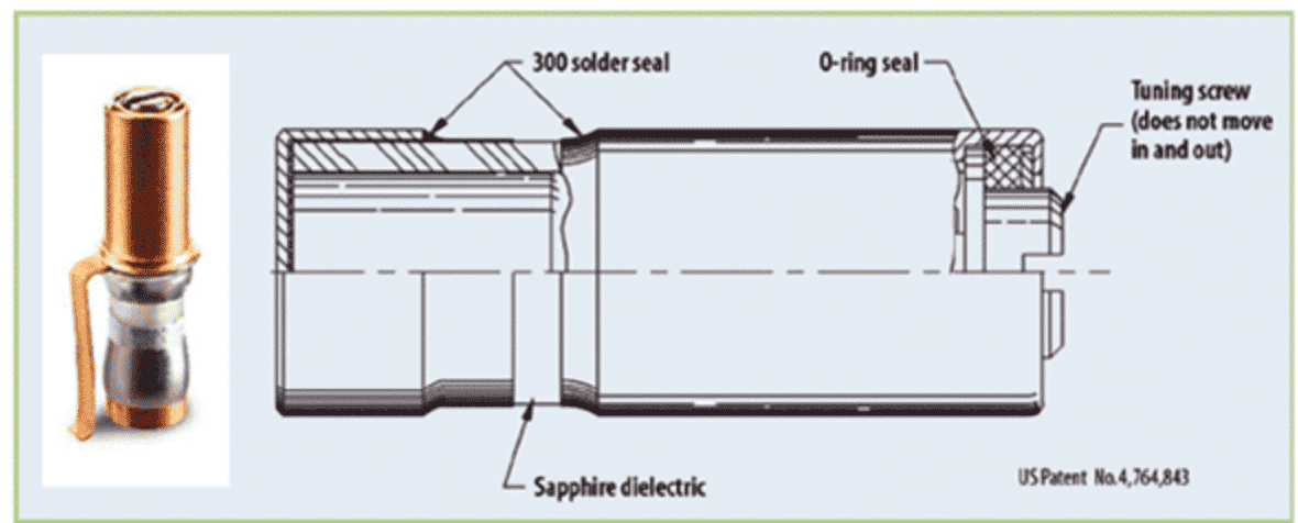
As a dielectric, sapphire is incredibly durable. The value of its dielectric constant does not change with frequency, it is mechanically strong and moisture resistant, and it features loss characteristics that are consistently low even above 10 GHz. For example, our Giga-Trim trimmer capacitor is built with sapphire as a dielectric, making it a virtually indestructible miniature trimmer with superior electrical characteristics. These capacitors can withstand the rigors of soldering heat, excessive tuning, and rough handling. As a result of the excellent dielectric and insulation properties of the sapphire housing, high breakdown voltage is also achieved.
Trimmer Capacitor Selection Guide – MRI Case Study
For sensitive applications like magnetic resonance imaging (MRI), trimmer capacitors help to optimize performance where any instability in time or temperature could impact the image output.
In essence, when a patient is positioned inside an MRI scanner tube and a magnetic field is applied, the proton spins inside their body’s molecules line up, facing the same direction. When a short, computer-generated RF signal is applied to a proton in the uniform field, it’s “nudged” to break formation. After the interruption, protons return to their original state of alignment. In the process of realigning, energy is emitted; the emitted energy can be measured and used to identify different types of molecules and their locations in the body. Trimmer capacitors are used to tune the TX and RX coils to Lamor Frequency, the frequency at which this energy is emitted. By extension, trimmer capacitor tuning is pivotal in MRI imaging accuracy.
In order to meet the high demand of MRI, important considerations for trimmer capacitor selection include:
| Q Factor | Influences power handling; higher Q lessens self-heating under RF conditions Important in filter circuits; impacts insertion loss |
| K Value (dielectric constant) | Determines the capacitance density in conjunction with dielectric withstand voltage; higher the K Value, smaller the component can be |
| Dielectric Withstand Voltage | The maximum DC voltage the part can withstand without failure |
| Non-magnetic Properties | Essential for MRI components, especially body coil and surface coils Close control of raw materials and processes required to ensure MRI accuracy and performance |
| Half-turn vs. Multi-turn Trimmers | Half turn trimmers have a lower Q, DWV, and precision; typically used in lower voltage and power environments where some tuning is required Multi turn trimmers boast higher Q, DWV, and performance; provides precision where exact tuning is imperative |
MRI components face severe non-magnetism requirements across components. In addition to careful material choices, Voltronics, a brand of Knowles Precision Devices (KPD), has developed a unique test setup to allow for Q and RF Voltage breakdown measurement at MRI operational frequencies. This has allowed for the development of parts designed specifically to meet the strict MRI requirements.
Understanding Trimmer Capacitor Specifications
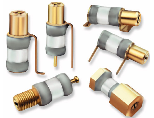
Once you have decided a trimmer capacitor is a good fit for your application, there are numerous additional decisions to make. In addition to the many dielectric options, trimmer capacitors are also available in numerous package styles, including those designed for PCB mounting, panel mounting, and surface-mount applications. Trimmer capacitors are even available for low-temperature applications in cryogenic systems and manufactured without magnetic materials for use in critical industrial and medical applications such as MRI systems.
There are also many specifications to consider when comparing trimmer capacitor options including capacitance range, the number of turns required to cover the capacitance range, the SRF, the minimum Q, temperature coefficient, tuning torque, DC working voltage, DWV, and size. When looking at these specs and comparing components from different manufacturers, it is important to normalize values for these characteristics as much as possible since manufacturers may use different reference points for measurements.

For example, when looking at Q, also note the frequency at which it was measured (which can range from 1 to 250MHz) as well as the capacitance at which it was specified. The higher the Q, the higher in frequency a trimmer will operate. Additionally, since Q is a function of frequency that decreases with increasing frequency, any comparison between trimmer capacitors from different suppliers should be referenced to a common frequency such as 1MHz or 100MHz. In addition, you should also note the capacitance value for the SRF, which may also be measured at any capacitance value within the tuning range.
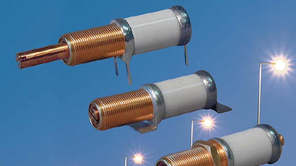
A trimmer capacitor’s maximum DC working voltage rating, which is the typical maximum value of continuous voltage for which that component is designed and tested, should also be considered. The DWV is typically twice the value of the maximum working voltage rating and is a short-term value above which damage will usually occur. The voltage rating generally depends on the size of the capacitor and the type of dielectric used in the trimmer capacitor, with high-isolation materials such as PTFE being capable of handling fairly high voltage levels. For example, our NT series of PTFE dielectric trimmer capacitors feature DC working voltage ratings as high as 7,500V and DWVs as high as 15,000V. These capacitors provide capacitance tuning ranges from 2 pF to 100 pF, although the high-voltage rating component is relatively large, measuring about 5 inches long (Figure 2).
While the operating temperature range needs to be a factor, you should also understand the effects of temperature on the trimmer capacitor’s set value as represented by the component’s temperature coefficient. The temperature coefficient presents a component’s amount of capacitance deviation in parts per million (ppm) per degree of temperature change. A smaller value temperature coefficient represents a more stable capacitor. When comparing models from different manufacturers, it is important to compare the temperature coefficient values for the same capacitance range. Additionally, for military applications, trimmer capacitors should be specified according to the required temperature range (–65 to +125°C) as well as to MIL-PRF-14409 specifications which call out screening of parts according to specific levels of mechanical shock and vibration.
Finally, when capacitor size is a crucial factor, there are low-cost chip-size trimmer capacitors available today that can replace fixed-value chip capacitors with little sacrifice in PCB real estate. Our Thin-Trim capacitors are ideal for applications where size and performance are most critical. These single-turn capacitors exhibit remarkable electrical characteristics for their small size and can be used for frequencies up to 2 GHz.

Capacitance Range and Tuning Capabilities
The capacitance range and the number of turns to adjust that range determine the amount of control over a capacitance setting. Trimmer capacitors are available in low-cost models with 1 pF to 2 pF of capacitance and one-half turn to units with tuning ranges to 250 pF and more and multiple turns of adjustment. Put simply, for more control, specify a trimmer capacitor with a greater number of turns for a given capacitance range. For example, our low-cost A1 Series trimmer capacitors includes models with maximum capacitance values of 4 pF, 8 pF, and 12 pF and seven turns for adjusting the two lower pF value models and 13 turns for adjusting the 12 pF model (Figure 3).
Tuning torque is simply a measure of the force needed to turn a trimmer capacitor’s adjustment screw. While this seems obvious, the value should be in a range that provides enough torque to ensure that an adjustment will remain in place once set, yet not so much torque it requires excessive force for tuning. This torque should generally fall in the range of 0.3 to 3.0 inch-ounces.
featured image: multi-turn trimmer capacitor; source: Knowles Precision Devices

