


Variable capacitors / trimmers and varactors are used for trimming and tuning purposes. They represent a small but important part of the capacitor assortment.
Key Takeaways
- Variable capacitors trimmers and varactors are essential components for tuning and trimming applications.
- Different designs include air dielectric, ceramic trimmers, plastic foil, and piston types, each with unique properties and applications.
- Varactors are diodes that provide voltage-controlled capacitance, useful in RF circuits and medical devices like MRI.
- Consider performance parameters such as Q factor, K value, and dielectric withstand voltage when selecting variable capacitors.
- Failure modes can impact performance; cleanliness and mechanical alignment are crucial for ensuring reliability.
General Description
Turning Types
By means of an electrode system consisting of one fixed and one movable part – stator and rotor – the capacitance can be varied between a minimum and a maximum value, the so called capacitance swing.
The temperature coefficient (TC) for the different occurring dielectrics usually differs considerably from the corresponding values for fixed capacitors. The variations are, except for what applies for the best precision components, considerably larger which has to do with the mechanical conditions that the whole construction is based upon.
Trimmer capacitors are mainly designed for mounting on printed circuit boards (PCB) but surface mount designs are getting more and more common. Trimmers often have a friction that increases the turning moment and thus locks the capacitor in its adjusted position.
Voltage Controlled Capacitors – Varactors
A varactor is a type of diode designed to exploit the voltage-dependent capacitance of a reverse-biased p–n junction. It is used as a voltage-controlled capacitor and is commonly used in voltage-controlled oscillators, parametric amplifiers, and frequency multipliers.
The word varactor is formed by the words: variable reactance or resistor variable. It provides a resistance, reactance or variable capacitance, which is why it is called a varactor diode.
Varactors are typically used in a wide variety of RF and Microwave circuits as tunable microwave devices.
Turning types
Air dielectric
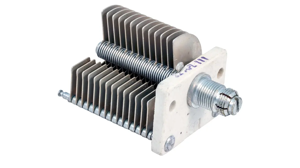
The classic variable capacitor consists of semicircular electrodes that can be turned into each other as shown in Figure 1. The styles are intended either for PCB or panel mounting. They are used preferably for tuning of resonance circuits.
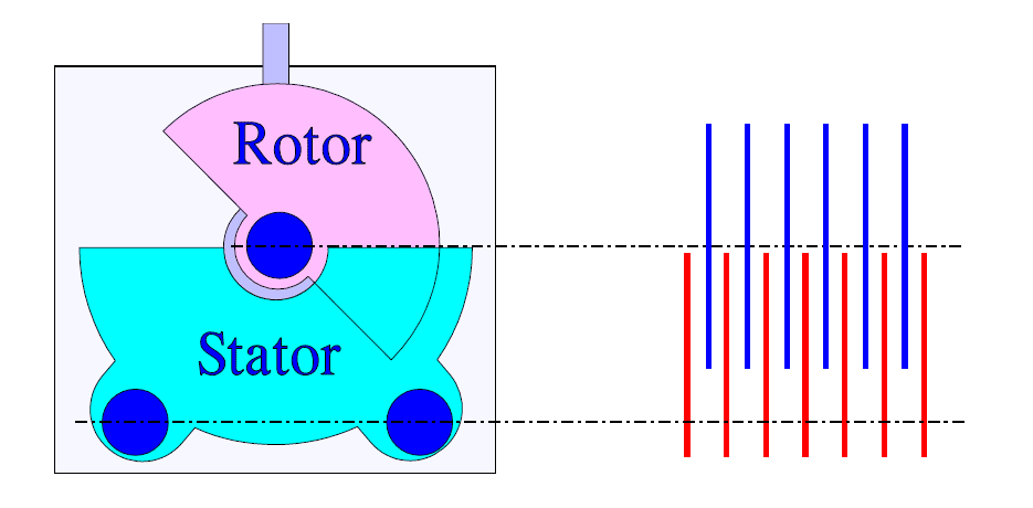
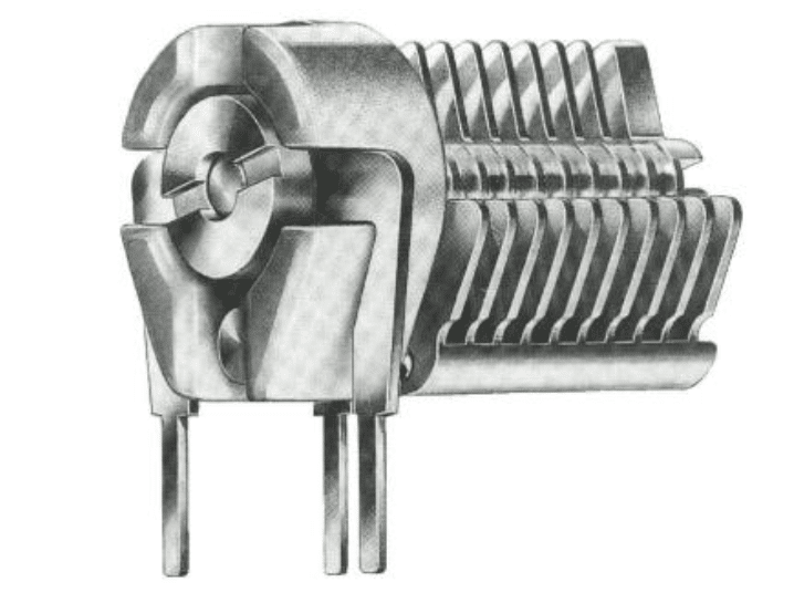
Figure 1. Schematic of an air-insulated variable capacitor and an example of Tronser’s make.
The air-insulated electrodes put great demands for mechanical precision. The plate distance usually is 0.2 to 1 mm. The price is relatively high.
Ceramic trimmers
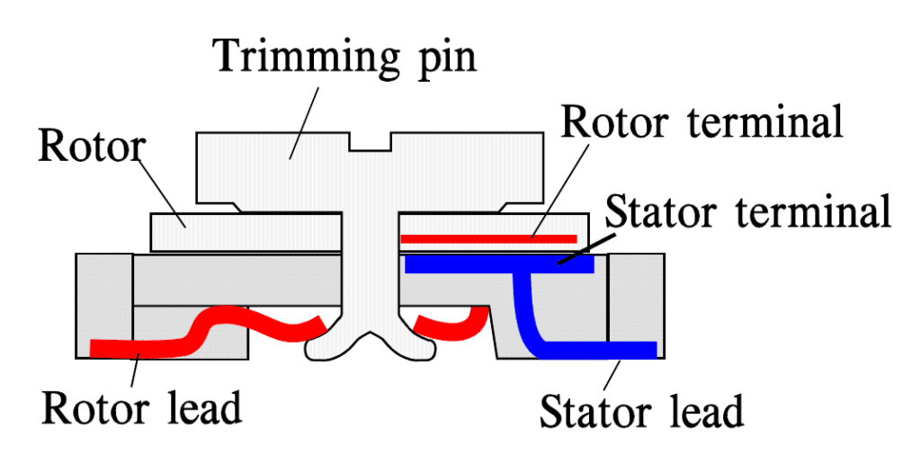
If we reduce the plates in Figure 1 to only one silver plated ceramic rotor that is turned in over the stator electrode we have got a ceramic trimmer capacitor. An example of this design is shown in Figure 2. Multilayer designs also exist. The capacitor styles are designed for either hole mount or surface mount.
Because Type 1 ceramics are used the losses will be relatively small.
Plastic foil types
If we exchange the air insulation in Figure 1. for some plastic foil the electrode distance can be decreased contemporaneously as the εr – and thus the capacitance, – increases, unfortunately to the trade off of a somewhat poorer Q value. Low loss plastics dielectrics like teflon (PTFE), polypropylene (PP) and polycarbonate (PC) are common but also polyester (PETP) exists.
Concentric design
In the concentric type air usually serves as dielectric. Rotor and stator are made from, for example, gold-plated brass. The concentric type consists of concentrically-orientated metal tubes on both the movable rotor and the stator.
They are inserted into each other from the rotor side and are separated from each other by an air gap. It is a matter of precision design that permits air gaps down to 0.1 mm (4 mils). The Q value will be high and the dimensions comparatively large. The temperature coefficient is very small.
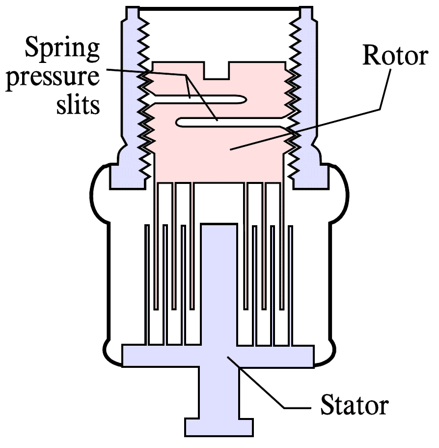
In order to get a setting stability one manufacturer uses one or several slits in the rotor that with spring force increase the friction and lock the trimmer in the adjusted position.
Piston design
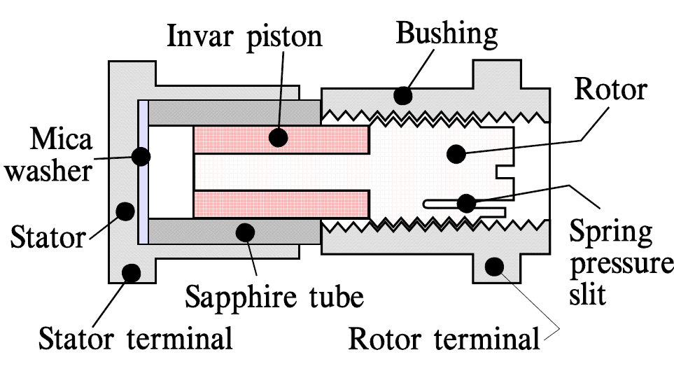
The piston design is used with air, teflon or sapphire as dielectric. With an εr of approximately 8 the sapphire dielectric achieves a certain capacitance per volume gain. Both hole and surface mount exist. A cross section through an SMD design with sapphire dielectric is shown in Figure 4. As for the concentric design the TC will be small.
Applications
Trimmers for commercial use sometimes lack satisfactory encapsulation. Then they must not be washed or exposed to solder fluxes or cleaning solvents. Encapsulated types with plastic housings should not be exposed to trichloroethylene.
For sensitive applications like medical magnetic resonance imaging (MRI), these components help to optimize performance where any instability in time or temperature could impact the image output.
In essence, when a patient is positioned inside an MRI scanner tube and a magnetic field is applied, the proton spins inside their body’s molecules line up, facing the same direction. When a short, computer-generated RF signal is applied to a proton in the uniform field, it’s “nudged” to break formation. After the interruption, protons return to their original state of alignment. In the process of realigning, energy is emitted; the emitted energy can be measured and used to identify different types of molecules and their locations in the body. Trimmer capacitors are used to tune the TX and RX coils to Lamor Frequency, the frequency at which this energy is emitted. By extension, trimmer capacitor tuning is pivotal in MRI imaging accuracy.
In order to meet the high demand of MRI, important considerations for trimmer capacitor selection include:
| Q Factor | Influences power handling; higher Q lessens self-heating under RF conditions Important in filter circuits; impacts insertion loss |
| K Value (dielectric constant) | Determines the capacitance density in conjunction with dielectric withstand voltage; higher the K Value, smaller the component can be |
| Dielectric Withstand Voltage | The maximum DC voltage the part can withstand without failure |
| Non-magnetic Properties | Essential for MRI components, especially body coil and surface coils Close control of raw materials and processes required to ensure MRI accuracy and performance |
| Half-turn vs. Multi-turn Trimmers | Half turn trimmers have a lower Q, DWV, and precision; typically used in lower voltage and power environments where some tuning is required Multi turn trimmers boast higher Q, DWV, and performance; provides precision where exact tuning is imperative |
Failure modes
Just as with potentiometers, variable capacitors are electromechanical creations with a correspondingly high failure rate. The contact resistance to the rotor can vary and produce contact disturbances.
Contamination – not the least from flux cleaning – may cause similar problems. Contamination and corrosion of mechanical parts may occur. Short circuits due to severe mechanical misalignment of air insulated parts are reported.
BST Varactors (Varactor Diodes)
Barium Strontium Titanate (BST) Varactors are the most often used types of varactors. Varactors are in fact type of diodes, but as the close links to the passive components technology it is included in this overview of passive components knowledge base. Searching for product types and features you may need to look for “varactor diode” references.
Barium Strontium Titanate (BST) thin film is classified as a ferrorelectric material and used as ceramic capacitors dielectric. Ferroelectric materials can be polarized with an applied external electric field then reversed. Without an applied electric field, the orientation of the materials dipole moment is in every direction. The polarity of the dipole moment changes in the direction of the applied electric field. It is this reversibility that makes ferroelectrics such a popular type of material for many applications such as tunable microwave devices.
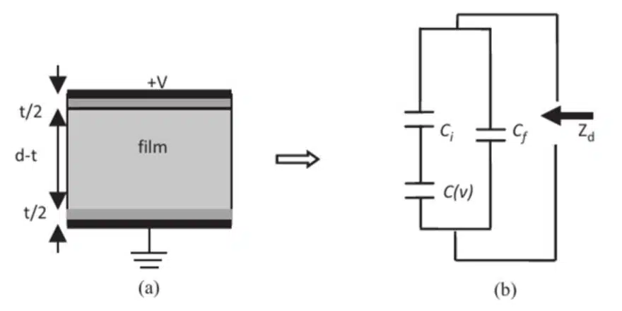
BST is a popular thin-film material for varactors because of its relatively high capacitance tuning ratio, low loss tangent, and high thermal resistance which is a result of being a ferroelectric material with an ideal Curie temperature point. See Figure 5. that illustrate BST varactor structure and schematic.
PierreCurie, a French physicist, discovered that ferromagnetic substances exhibit a critical temperature transition, above which the substances lose their ferromagnetic behavior and become paramagnetic. This is known as the Curie temperature. In analogy to ferromagnetic and paramagnetic materials, the Curie temperature can also be used to describe the phase transition between ferroelectricity and paraelectricity.
The Curie temperature is the point where the ferroelectric crystal changes phase. Below the Curie temperature, the crystal is in a polar phase and exhibits a field dependent polarization hysteresis loop. Because of this hysteresis, a given permittivity value of the crystal can have more than one applied DC field value. Above the Curie temperature, the crystal is in paraelectric phase with no hysteresis present and the permittivity of the crystal may be determined unambiguously via an applied DC field value. For this reason, and that hysteresis causes an increase in dielectric loss2, most devices are designed to operate in the paraelectric phase region.
The slope of the polarization vs. electric field curve gives the relative dielectic permittivity of the ferroelectric material. The advantage of having a Curie temperature point around the device operating temperature is it gives BST its highest dielectric constant, low loss tangent and linear tuning. The chemical formula of BST is BaxSr1-xTiO3.
The Curie temperature can be adjusted by varying the barium and strontium concentrations. If the Barium concentration is kept at 0.6 and below (x<0.6), then the Curie temperature of the BST material will be well below room temperature. This concentration ensures devices operate in the paraelectric phase at room temperature.
Applications for BST materials in RF/Microwave systems are numerous. BST varactors are key elements in tunable filters, frequency selectable resonators, matching networks, delay lines and steerable directional antennas. In addition to being able to change the dielectric permittivity of the material, another benefit is fast tuning speed. Tuning speeds have been reported in the nano-second range and is faster than other technologies such as MEMS, semiconductor varactor technologies and PIN-diode based structures.
Variable Capacitors, Varactors and Trimmers – FAQ
Variable capacitors are electronic components whose capacitance can be adjusted. They typically consist of a stator (fixed part) and a rotor (movable part), enabling the capacitance to swing between minimum and maximum values. They are used for trimming and tuning in radio frequency circuits and PCB designs, including trimmers and varactors.
Main types include air dielectric, ceramic trimmers, plastic foil, concentric, and piston designs. These types differ in materials, precision, Q value, and mounting styles.
They are used in RF and Microwave circuits, voltage-controlled oscillators, parametric amplifiers, frequency multipliers, and specialized fields such as medical MRI equipment where stability and tuning are critical.
Varactors are diodes that use the voltage-dependent capacitance of a reverse-biased p–n junction, commonly used as voltage-controlled capacitors in tuning applications.
Failure modes include variable contact resistance, contamination from cleaning agents, corrosion, and misalignment. These can cause instability or short circuits in sensitive applications.
How to Select and Use Variable Capacitors for RF and Medical Applications
- Determine Requirement
Decide if you need trimming, voltage control, or precision tuning for your application (e.g., MRI, RF circuits).
- Choose Type
Select between air dielectric, ceramic trimmers, plastic foil, concentric, or piston designs based on Q factor, dielectric, and mounting style.
- Check Encapsulation
For commercial or medical use, choose well-encapsulated types to resist cleaning agents and environmental effects.
- Review Performance Parameters
Compare Q factor, K value (dielectric constant), dielectric withstand voltage, and non-magnetic properties for medical precision.
- Installation
Mount trimmer or varactor as recommended (PCB or surface-mount). Ensure correct positioning to avoid mechanical misalignment.
- Tune and Test
Adjust the capacitance to the desired value. Test the stability over temperature and in target application (especially critical for RF/MRI).
- Monitor for Failure
Regularly check for contact resistance changes, contamination, or corrosion to maintain performance.
- Design Tips
In MRI, tune to Lamor Frequency for optimal imaging accuracy.
For highest Q and performance, choose multi-turn trimmers.
BST varactors offer fast tuning speeds, important for RF/microwave systems.


