Capacitors, as fundamental passive components, possess characteristics far from their ideal models. One of the most critical non-ideal parameters is Equivalent Series Resistance (ESR), which directly influences capacitor energy losses, performance, thermal management, and reliability across applications from power supplies to RF circuits.
This post explains the essential concepts, mechanisms, and practical guidance on ESR of capacitors, providing an advanced resource for engineers and designers.
Key Takeaways
- Equivalent Series Resistance (ESR) significantly affects capacitor performance, influencing energy loss and reliability in various applications.
- Understanding ESR requires knowledge of loss mechanisms, including dielectric losses, conduction losses, and interfacial polarization.
- Selecting the right capacitor technology based on ESR characteristics is crucial for optimal performance across frequency ranges.
- In applications like switching power supplies, combining different capacitor types helps manage ESR effectively across varying conditions.
- Engineers must measure ESR under actual circuit conditions to ensure component stability and reliability.
Physical Models & MathML Equations for ESR
A capacitor creates in AC circuits a resistance, the capacitive reactance Xc. There is also certain inductance in the real capacitor. In AC circuits it produces an inductive reactance XL that tries to neutralize the capacitive one. Finally the capacitor has resistive losses . Together these three elements produce the impedance, Z.
If we apply an AC voltage over a capacitor its losses release heat. They can be regarded as a resistive part of the impedance, i.e., as resistive elements distributed in different parts of the component, e.g. in accordance with the equivalent circuit in Figure 1.
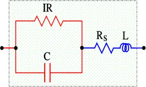
- C = Capacitance
- IR = Insulation Resistance (IR>>Rs)
- Rs = Series losses
- L = Inductance in lead-in wires (ESL)
Rs consists of resistance in lead-in wires, contact surfaces and metallized electrodes, where such elements occur, as well as dielectric losses. If we apply a DC voltage over the capacitor, the generator ”feels” a purely resistive loss dominated by the IR. But because of the high value of the IR the heat release will be negligible. Should we instead change over to an AC voltage and let the frequency rise the current will increase proportionally and eventually release a considerable heat in the Rs. If we transform the IR to a small series resistance and join it with the Rs we get a total series resistance called ESR (Equivalent Series Resistance, sometimes called Effective Series Resistance). The series impedance, Zs, in Figure 1. can be written:

As a root mean square value we obtain the formula:
The capacitive reactance Xc = 1/ωC, in the formula above decreases with frequency to that level where the inductive reactance, L, takes over. It happens at the resonance frequency fo of the capacitor where 1/ωC = L. Above the resonance frequency the capacitor is inductive. Exactly at the resonance frequency remains of the impedance Z only the resistive ESR (Figure 2.). By determining the losses at the resonance frequency we gain accuracy. But there is a condition for this accuracy. We need to know the frequency dependence of the ESR which very much is conditioned by the dielectric material. In certain materials it is negligible, in others considerable.
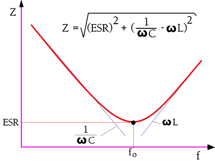
At the resonance frequency, the reactive components cancel, and only ESR remains, becoming a critical loss metric. The frequency response curve shows a sharp minimum (for low-loss caps) or a broader dip (for high-loss types)—impacted by the ESR value and type.
Dissipation Factor and Quality Factor Relation to the ESR:
ESR and Loss Mechanisms in Capacitors
Complexity of Loss Mechanisms: ESR in capacitors stems from interplay of various physical phenomena. Besides simple conductive losses, it encompasses dielectric relaxation (microstructural effects such as porosity and grain alignment), ferroelectric hysteresis, interfacial polarization, partial discharge, skin effect of metal electrodes, sparking, electromechanical phenomena (electrostriction, piezoelectricity, Lorentz force-induced wire flexing), and eddy currents. Each mechanism exhibits distinct dependencies on voltage, frequency, temperature, and even pulse shape.
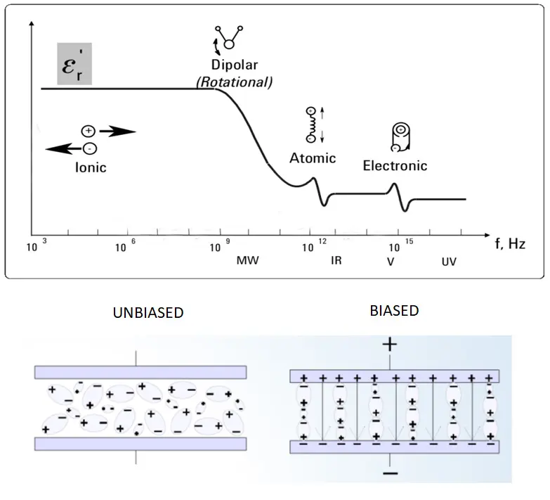
Dielectric losses
Different dielectric materials respond differently when voltage is applied or removed. Dielectric losses are associated with how dielectric materials polarize or relax in response to voltage. The magnitude of these losses depends on both temperature and frequency. The dissipation factor (DF) is commonly used to describe the dielectric losses of a material (at low frequencies). The dissipation factor and equivalent series resistance of a capacitor are dependent on the electrodes as well as their configurations.
Dielectric conduction losses refer to losses that are caused by the actual movement of charge across a dielectric material. These losses tend to be largest at high temperatures and low frequencies.
Ohmic resistance losses
Metallic terminals, electrodes, and internal wiring of capacitors exhibit resistance. This energy loss does not vary significantly with temperature and frequency. However, at high frequencies, the skin depth effect in electrodes becomes significant. Although ohmic resistance losses occurring within terminals and internal wiring are insignificant in low current applications, they should not be ignored in high current applications.
Ferroelectric hysteresis losses
Some high dielectric constant materials exhibit losses that are strongly dependent on applied voltage. These losses are referred to as ferroelectric hysteresis losses, and they occur when the internal polarization field and the applied field have the same magnitude. This condition causes saturation of the dielectric material. Capacitors that have such high dielectric constant materials exhibit sensitivity to voltage reversals, permanent polarization, and variation of capacitance with voltage. Ferroelectric hysteresis losses are common in ceramic capacitors with high dielectric constant materials.
Interfacial polarization losses
The dielectric systems of most high voltage capacitors have at least two different materials. Each of these materials has different permittivity and conduction properties. This difference in properties causes accumulation of charge at the internal interfaces of such materials when a DC voltage is applied. Interfacial polarization losses are common in low-frequency high voltage capacitors.
Partial discharge losses
Some capacitors exhibit partial discharges when they are exposed to high rates of voltage change. This energy loss mechanism is referred to as partial discharge loss, and it is common in gas filled capacitors and liquid-filled capacitors, most notably at high voltages. Partial discharge losses can also be caused by voltage reversals.
Eddy currents
In capacitors, eddy current losses are strongly dependent on frequency. In most applications, this energy loss mechanism has an insignificant effect, and it is usually ignored. However, in pulse forming networks, eddy current losses have a significant effect and should be considered.
Sparking
In some capacitors, sparking can occur during discharge.Sparking occurs mainly between adjacent metallic surfaces, and it is a common energy loss mechanism in pulse capacitors. This energy loss mechanism is dependent on both voltage and frequency.
Electromechanical losses
In most capacitors, electromechanical losses occur mainly within the dielectric material and the internal wiring. In the dielectric material, electromechanical losses are primarily caused by electrostriction. In some cases, it may be caused by piezoelectric effect. In internal wiring, Lorentz forces can cause flexing. When this happens, it leads to energy losse
| Mechanism | Description | Dependency | Impact |
|---|---|---|---|
| Dielectric Losses | Polarization relaxation, microstructure effects | ↑T, ↑f, material type | Heats dielectric, limits life |
| Conduction Losses | Charge movement in dielectric | ↑T, ↓f | Dominates low-freq ESR |
| Ferroelectric Losses | Hysteresis in polarization (ceramics) | Voltage, material (BaTiO3) | Leads to capacitance variation, instability |
| Interfacial Polarization | Charge accumulation at material interfaces | Multilayer structures, high voltage | Relevant for HV film/ceramic caps |
| Ohmic Resistance | Wires, electrodes, terminations | High current, construction quality | Thermal heating, critical in pulse applications |
| Skin Effect | Current crowding at conductor surface | High freq (>1MHz) | Raises ESR at RF, affects Q |
| Sparking | Discharge between metal surfaces | Pulse shape/voltage/freq | Short-term energy loss, reliability threat |
| Electromechanical Losses | Electrostriction, piezoelectricity, wire flex | Pulsed operation, composition | Increases ESR in fast, high-current circuits |
| Eddy Currents | Induced circulating currents | ↑f, thick metal structures | Relevant for pulse forming networks |
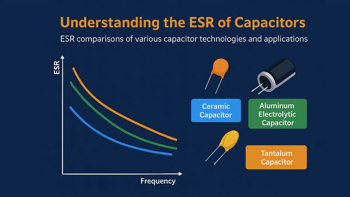
ESR in Capacitor Technologies
Frequency Behavior: At low frequencies (50Hz–1kHz), dielectric and conduction losses dominate; mid frequencies (1kHz–10kHz) observe construction and electrolyte effects (electrolyte capacitors). Above 100kHz, ohmic and skin effect rule. ESR typically decreases with frequency, but each technology has a distinct curve (see below).
| Freq Range | Dominant ESR | Ideal Capacitor | Note |
|---|---|---|---|
| 50Hz–1kHz | Dielectric/conduction | Aluminum, Tantalum | Batteries, legacy AC |
| 1kHz–10kHz | Electrolyte/construction | Hybrid Al, Polymer Ta | DC-DC, automotive |
| >100kHz | Ohmic/Skin effect | MLCC Class I | High-speed, RF |
ESR is used to characterize capacitors losses mainly in higher frequency domain with standard reference frequency at 100kHz. ESR with frequency chart is illustrating losses in the entire frequency spectrum. As discussed above, the low frequency losses below around 1kHz are driven by “slower” polarization and losses in dielectric layers, mid frequencies (~ 1kHz to 10kHz) are driven by internal construction losses (such as conductivity of internal structure and electrolyte), the high frequencies >100kHz are driven by mostly ohmic losses of terminations, contacts etc.
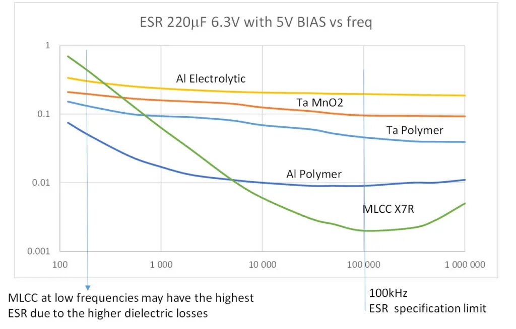
Referring to Fig.4. MLCC capacitors are exhibiting lowest ESR values compare to other technologies referred to a standard specification frequency 100kHz thanks to its multilayer structure. This is a beneficial for smoothing of higher frequencies and fast spikes for applications such as switching power supplies. However, at low frequencies, MLCC class II capacitors are featuring higher ESR(and DF) compare to other technologies. Thus in practical example in case of low frequency spike present (such as 50-216Hz often seen) it is more efficient to use the MLCCs in parallel with some aluminium or tantalum electrolytic capacitors.
- MLCC capacitors (Ceramic, Multilayer):
- ESR is shaped by dielectric microstructure (grain size, porosity, composition) and metallic terminations.
- Class I dielectrics (e.g., C0G, NP0): lowest ESR, stable across voltage/temp/freq.
- Class II (e.g., X7R, Y5V): higher ESR/DF at low freq and low voltage, strong voltage/freq dependence. Microstructure impurities, porosity increase losses.
- Skin effect in RF degrades Q for high-current applications.
- Susceptible to piezoelectric electromechanical effects in SMD assembly.
- Tantalum Capacitors:
- Oxide layer thickness controls voltage rating and influences insulator losses.
- Two main cathode types: MnO2 (higher ESR, temp-dependent) vs. conductive polymer (low stable ESR).
- Conductive polymer types have stable ESR vs. temperature, minimal drift at −55°C and below, critical for automotive/aerospace.
- Dielectric absorption, leakage current, and partial discharge present at very low frequencies (<1 Hz).
- Parallel connection of multiple tantalum capacitors can lower ESR for high-pulse/decoupling needs.
- Aluminum Electrolytic Capacitors:
- Paper and electrolyte are leading contributors at low frequency; tabs and foils at high frequency.
- Hybrid designs (polymer-wet electrolyte): lowest ESR, improved reliability (less dryout, longer life).
- Thinner, less-dense separators, more tabbing, high-conductivity electrolyte reduce ESR.
- Ripple current capacity increases as ESR decreases, making low-ESR types key for high-current filtering.
- Temperature rise from ESR-induced heating is a major failure mechanism—thermal runaway risk at high ripple.
| Technology | ESR at 100kHz (Low) | ESR at 1kHz (High) | Best Use Case |
|---|---|---|---|
| Ceramic MLCC (Class I) | Very Low | Very Low | RF, high-speed, timing |
| Ceramic MLCC (Class II) | Low | Moderate to High (especially at low voltages) | Filtering, bypass, bulk in parallel array |
| Tantalum (Polymer) | Low, stable | Low, stable | DC-DC converters, automotive, pulse |
| Tantalum (MnO2) | Higher, temp sensitive | Higher, temp sensitive | Historic LDO, legacy op-amp |
| Aluminum Electrolytic | Low (polymer/hybrid) | Higher (wet/electrolyte) | Bulk smoothing, high ripple load |
Application Impact and Selection Guidance
- In switching power supplies, parallel MLCC and electrolytic capacitors optimize ESR across wide frequency range and ripple spectra.
- Tantalum polymer capacitors maintain lower ESR in wide temperature range compared to MnO2 types.
- Ripple current ratings are closely linked to permissible ESR in electrolytics; higher ESR leads to thermal breakdown and reduced life.
- For ultra-low ESR, paralleling multiple MLCCs spreads heat and reduces impedance peaks, but increases PCB space and risk of cumulative piezo noise.
- LDO regulators and op-amps may require specific ESR range—excessively low ESR can destabilize feedback loops (especially legacy designs).
- Switch mode power supplies (SMPS): Combine MLCC (fast transient) and electrolytic/tantalum (bulk ripple) to flatten overall ESR across load spectrum.
- In automotive and industrial, polymer types ensure ESR stability at −40° to +125° C for mission-critical reliability.
- For RF, Millimeter-wave, and high-Q resonant circuits, prioritize class I ceramics or low-ESR film capacitors.
| Application | Preferred ESR Range | Capacitor Tech | Why? |
|---|---|---|---|
| Op-amp feedback | 10–100mΩ (legacy ICs) | Tantalum MnO2 | Stabilizes loop, avoids oscillation |
| Modern LDO | Ultra-low–moderate | Polymer, MLCC | Chip robust to ESR drift |
| SMPS output | Ultra-low broad spectrum | MLCC (parallel), hybrid Al | Wide ripple suppression |
| Pulsed DC, automotive | Low, stable over temp | Polymer tantalum | Reliability at extremes |
Advanced Design and Measurement Insights
- For lab measurement: Use parallel Cp settings for high-impedance values >10kΩ (small C), Cs for <10Ω (large C). DF/tanδ for low-frequency, ESR for high-frequency characterization.
- Prototyping: Always validate ESR under real circuit conditions considering variables such as temperature, ripple current, and mounting method (SMD stress). Use manufacturers simulation tools to check ESR in whole operating conditions range.
- Field reliability: Excess ESR can cause local overheating, dry-out (aluminum electrolytics), or explosive failure (especially in electrolytics). Monitor ESR drift as part of preventative maintenance.
| Technology | Low-Freq ESR | High-Freq ESR | Application Suitability |
|---|---|---|---|
| MLCC (Ceramic) | Higher (Class II) | Very Low | RF, high-speed, precision |
| Tantalum | Medium (polymer > MnO2) | Low | Stable power supply, decoupling |
| Aluminum Electrolytic | Low | Higher than MLCC | Bulk filtering, power smoothing |
Case Studies and Industry Practices
- High DF at low frequency signals possible dielectric issues (impurities, delamination).
- High ESR at high frequency usually implies problems in connections (e.g., welds, terminations).
- Reliability studies show polymer/hybrid aluminum electrolytics outperform conventional wet electrolytic designs in long-term ESR stability and thermal resilience.
Further Read Reference:
Understanding the Influence of ESR and Ripple Current for the Capacitor Selection
Conclusion
ESR is a pivotal parameter underpinning the performance, efficiency, reliability, and safety of capacitors in electrical circuits. Thorough understanding of loss mechanisms, technology differences, and practical application constraints enables optimal component selection and robust design. Engineers must reference datasheets, measure ESR under real-world conditions, and tailor selections to circuit needs, balancing low loss with required minimum ESR for stability.
FAQ: Capacitor ESR
ESR (Equivalent Series Resistance) is the real, resistive part of a capacitor’s impedance, caused by leads, electrodes, connections, and dielectric material. Low ESR minimizes heat and loss, improving efficiency and reliability in demanding circuits.
ESR exclusively measures resistive losses, while DF (or tanδ) reflects both resistive and reactive (frequency-dependent) losses as a ratio of ESR to capacitive reactance. DF is typically used at low frequencies, ESR at high frequencies.
Losses lead to heat, voltage drops, reduced efficiency, and can shorten lifespan or reliability. Understanding ESR and its impact across frequency, temperature, and voltage is vital for application-appropriate component selection.
MLCC (ceramic) capacitors have the lowest ESR at high frequency, tantalum with polymer cathodes provide stable low ESR, and aluminum electrolytics (especially hybrid and polymer types) are optimized for high bulk filtering with moderate ESR performance.
For large capacitance (impedance below 10Ω), use series (Cs) mode; for small capacitance (over 10kΩ), use parallel (Cp) mode on measurement bridges. Refer to datasheets for specified test frequencies (typically DF at 120Hz or 1kHz, ESR at 100kHz).
Some Low-Dropout Regulators (LDOs) or amplifier circuits necessitate a minimum ESR for stable operation. Excessively low ESR can lead to control loop instability, so it’s crucial to verify the requirements from the IC datasheets. This is particularly important when adopting wide-gap semiconductors like Gallium Nitride (GaN) or Silicon Carbide (SiC), which have lower resistance circuits that can induce spikes and current surges. Such circuits must be designed to be robust and suppress oscillations to address these challenges.
How-To: Measure Capacitor’s ESR
- Identify Capacitance and Target Frequency
Check the capacitor’s datasheet for the recommended measuring frequency and expected ESR value (e.g., 100kHz for ESR, 120Hz/1kHz for DF). Note the rated and operational voltage, and set the correct measurement DC BIAS. (For polarized capacitors, ensure that the AC measure voltage is smaller than the set DC BIAS voltage.)
- Set Up Your LCR Meter or Bridge
Choose series (Cs) mode for low-impedance (large capacitors), or parallel (Cp) mode for high-impedance (small capacitors). Connect probes with minimum lead length to avoid stray resistance.
- Calibrate and Zero Equipment
Insert the capacitor into the measure jig and allow the meter to stabilize. Record ESR (or DF), noting the measured frequency and environmental conditions (temperature, humidity). Note dependency of MLCC capacitors on DC BIAS and AC voltage.
- Interpret and Compare Results
ompare results to the datasheet’s reference values. If ESR is higher than specified, check for aging, connection faults, or inappropriate measurement settings. Check the manufacturer’s simulation tools.