

Tantalum capacitors are the preferred choice for applications requiring the highest energy density, best reliability, low ESR, and excellent stability over wide ranges of time and application temperatures.
This paper shows the latest status of newly developed powders that extend the range of forming voltage to 300 V and 400 V and thus enables extension of tantalum capacitor voltage ranges to new applications and circuits.
The paper was presented by Melanie Stenzel, Taniobis, Germany at the 4th PCNS 10-14th September 2023, Sønderborg, Denmark as paper No.2.2.
Recently, the demand of high reliability capacitors withstanding harsher conditions and higher application voltages has increased. The main driver for such applications is often aviation/aerospace, automotive (driver assistance systems, e-vehicles) and transportation, medicine (defibrillators) and defense, but also consumer electronics for SSD data storage.
Taniobis continuously improves its portfolio of high voltage powders and is expanding the tantalum capacitor technology to new fields of application. The “High Voltage Medium Capacitance” (HVMC) powders have a unique combination of structural homogeneity, high purity and tailored pore structure to provide the highest capacitance of Ta powder for the formation voltage (Vf) range >80 Vf. We will show the latest status of newly developed powders that extend the range of forming voltage to 300 V and 400 V.
Moreover, new options to further improve the pore structure results in an increased capacitance at a given forming voltage. Beyond powder design, the impact of anode processing to master such high anodization voltages is highlighted.
Introduction
Moore’s law predicts that the number of transistors in a dense integrated circuit doubles about every two years [1]. This law describes the impressive speed of miniaturization but also the performance increase of electronic parts. Likewise, the performance of tantalum capacitors is continuously improved but at a slower pace. For high voltage applications an unceasing and increasing demand for powders optimized for applications voltages >35 V is observed.
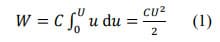
These capacitors are used for different fields of application, often connected with high reliability: consumer electronics (SSD, charging devices, etc.), transportation and automotive, signal transmission for railway, medical devices (e.g., implantable cardioverter defibrillators), defense and aerospace (aircraft and satellites). There are different trends that we have recognized in recent years: 1. Demand for increased stored charge in a given volume at a given voltage, e.g., more capacitance at 150 V forming voltage not reachable with standard Ta powders to create new capacitor types for new applications. 2. Demand to further increase the forming voltage above 300 V since the energy W that can be stored by a capacitor is correlated with the voltage U squared:

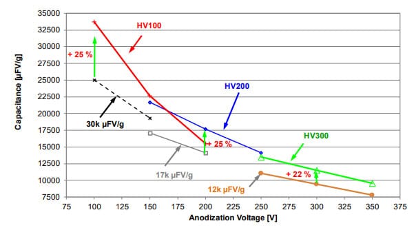
HVMC powders provide the required capacitance at forming voltages in the range of 100-350 V and are compared to standard tantalum capacitor powders, as shown in fig.1. At any voltage in this range, there is at least one powder type that has more capacitance and energy density than comparable standard powder types. It was already shown that the key for the excellent high voltage range of HVMC powders is the improved microstructural homogeneity with respect to pore and primary particle sizes [2, 3].
The tighter primary particle distribution allowing higher capacitance is the result of extensive research to optimize the parameters of our production processes. We have developed multiple different HVMC powder types, since each anodization voltage has its own optimum concerning primary particle and pore size distribution. To simplify the powder naming we have decided to put the classification (“HV” = High Voltage) and the recommended optimum forming voltage in its name (like HV200 – developed for 200 Vf) in contrast to the conventional naming where the capacitance (mostly measured at lower voltages) is included.

The purpose of this paper is to show our general approach how to improve the microstructure regarding higher capacitance at a given formation voltage exemplified by our newly developed HV150 powder and how to extend the range of anodization up to 400 V by referring to our latest development, HV400 powder. Improvements in pressing technique are done to support further the high voltage and reliability performance of capacitors. The impact of the anodization technique when reaching 400 V is significant and has, like the powder itself, to be optimized to realize new types of capacitors in the future.
Discussion
How to provide more capacitance by tailoring the microstructure?
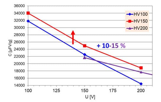
The microstructure of the tantalum powder is the key for realization of higher volumetric capacitances and must be tailored for each anodization voltage range to its optimum [2]. Currently, new capacitors with anodization voltage of ~150 Vf are highly requested. At 150 V anodization our products HV100 and HV200 show nearly comparable capacitance in electrical wet tests (see fig.2). However, due to its smaller pores as shown in fig. 3, capacitors made from HV100 will show worse impregnation and ESR behavior compared to those made from HV200 having larger pores. That’s why HV200 would have been the powder of choice for 150Vf in the past.

Our task was to develop a powder with distinctly higher capacitance than the HV100 and HV200 products in the range Vf=100-200 V by improving the particle and pore size distribution of the powders. To achieve this the Mg reduction process, proprietary to Taniobis and key step of the HVMC powder production route, needed to be enhanced. The pore size distribution of sintered anodes is considered as a suitable evaluation method because it demonstrates the influence of the pressing and sintering step on the powder structure.

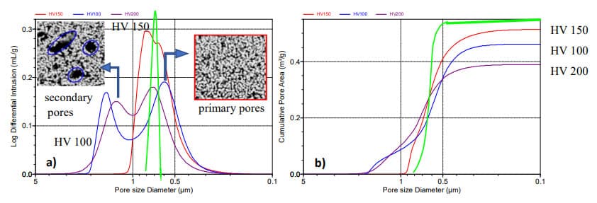
Anodes made from HV100 and HV200 have both a bimodal pore size distribution. The smaller “primary” pores (maxima at 580 nm for HV100 and at~720 nm for HV200) are responsible for the surface area of the porous anode body and therefore correlating to the capacitance. The larger “secondary” pores (maxima at 1540 nm for HV100 and at 1310 nm for HV200) representing the empty space between adjacent agglomerates. By adjusting our processes, it was possible to modify the pore size distribution for the new HV150 powder significantly. Anodes made from this new powder show a nearly monomodal pore size distribution and the maximum of the primary pore size is adjusted to 660 nm, i.e. between those of the maxima for HV100 and HV200 anodes. To make best use of these optimizations, a homogeneous density distribution along all axis of the anodes is also beneficial. The outside of the anode is especially critical, as high-density surfaces can hinder the impregnation of liquid electrolytes and polymer.
The improved microstructure has a direct impact on the capacitance behavior (see fig. 2). At 150 Vf this powder provides 10 % more cap than the HV100 powder and 15 % more cap than HV200 powder. It is interesting that at 100 Vf and even 200 Vf this powder results in the highest capacitance – this reflects its enhanced uniformity that causes such stable capacitance slope. This is supported by the fact that the slope of the capacitance as a function of formation voltage for the HV150 anodes is not steeper than that for the HV100 anodes, but it is parallel.
This shows the general approach how to tailor capacitor powders to higher and higher capacitances in the future! To provide even more capacitance at 150 Vf the pores of future powders and anodes must be as narrow as possible. In fig. 3 this is suggested by the green curve – the smaller and higher the pore peak the higher the feasible capacitance at a given voltage! It was already shown by a simple mathematical calculation [2] that for a perfect homogeneous anode structure consisting of uniform cylinders of the same size a maximum capacitance of 52kµFV/g @ 100 V and 34 kµFV/g @150 V can be achieved. This is still far away from today’s available capacitors and shows the potential that could be realized with a powder having an even more improved microstructure in the future.
It should be noted that anode size and density should also factor into the decision of powder type. For the powder types listed, a nominal anode size of ~0.100g is used and a final density of approximately 6.0g/cc. For larger anodes between 1-20 grams, selecting a higher voltage powder with larger pores is often preferred as longer pore distances can impact formation cooling and ESR values, which affect capacitance. Similarly, if higher sintered densities and shrinkages are targeted, the overall pore structure will be smaller and using a higher voltage powder with larger nominal pores is often beneficial. While the highest ‘nominal’ capacitance would predict the best capacitance for an HV150 powder, a more massive or denser anode may require a higher voltage powder (HV200) to maintain ideal porosity for processing.
Next generation of high(est) voltage powder: HV400
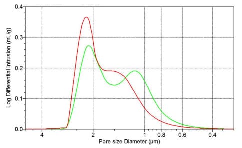
The HV300 product is mainly used for anodization voltages in the range of 250-300 Vf and is approved as a powder for highest reliability applications like medical and aerospace. It was proven by capacitor manufacturers that this is the tantalum powder enabling capacitors with the highest energy density currently available. The target of further increasing the energy density according to equation (1) was the driving force for the development of an HV400 that can be anodized up to 400 V. Therefore, again the powder microstructure must be adapted: both, primary particle size as well as the medium pore size must be increased. The higher anodization voltage will “consume” more tantalum that is converted to Ta2O5 film which in turn needs more space than a film formed at 300 Vf. A direct comparison of the pore structure of anodes made from HV300 and HV400 powders with identical pressing and shrinkage conditions can be seen in fig 4. The maximum of the primary pore peak has been shifted from 1200 nm to 1600 nm while the secondary pore peak position has not significantly changed. The primary difference is that the pore size distribution of anodes made from the new HV400 powder is narrower than that of anodes made from HV300 powder – primary and secondary peak position are closer, the distribution is “less” bimodal.
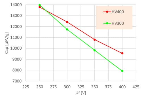
Anodes of both HVMC powders were used for anodization from 250 to 400 V with the same formation program. At 250 Vf, the HV300 powder has a slightly higher capacitance, but for voltages above 260 V the HV400 has a higher capacitance (fig. 5). At 400 Vf anodes made from HV400 powder show 9550 CV/g, an increase by 20 % when compared to those made from HV300 powder. The slope of the HV400 capacitance curve is less steep than that of the HV300 – meaning it is more stable and could be used for even higher anodization voltages.


The microstructure of an HV400 anode formed at 400 V still shows open pores, and an oxide film with an impressive thickness of ~760 nm suggesting that such a powder could be capable to reach even higher voltages (fig. 6). However, an increase of the leakage current to values >10 nA/µC at higher voltages limits a further anodization to 450 V due to the occurrence of oxide film breakdown. Since we could not find any breakdowns or oxide defects after 400 V anodization by intensive SEM investigations, it is assumed that the quality of the oxide film anodized in our current standard electrolyte recipe (glycol/water/H3PO4) is not good enough to withstand such high voltages. Therefore, we also have started to investigate the anodization process further and its influence on the oxide structure.

Improvement of anode fabrication with new pressing technique
The microstructure (primary grain and pore structure) of anodes produced from tantalum powders can be improved by our new development of HVMC powders. However, of equal importance is the proper pressing and sintering of the tantalum anodes. These are processed with top-bottom or transverse pressing (side-press) techniques. Depending on their size and target density, the anodes show press gradients with higher densities at the outside. High densities and increased press stroke result in increased burnishing of the anode surface. This disadvantage can be minimized by using pressing aids (lubricants/binders), but cannot be avoided completely. In addition to increased burnishing, the pickup of impurities from the pressing tool by abrasion has a direct impact on the final electrical performance of the tantalum capacitors (high leakage current).
To provide the best solution to our customers, we started a collaboration with HD Mechanic GmbH which developed a pressing machine with newly developed method of perimetric compression. Perimetric compaction differs from the known techniques, in that it involves simultaneous compaction in both body axes orthogonal to the incorporated tantalum wire. Compared to conventional methods, the perimetrically compacted anode bodies are characterized by lower weight and dimensional tolerances, as well as less surface compaction (burnishing).
The first results show an improved surface quality and less density variations within the anode. With a flexibility of pressing parameters of speed, stroke and direction, the optimum pressing procedure can be determined for different pellet conditions.
In addition, this press can process both bindered and non-bindered powders with high process reliability. The possibility of pressing without binder reduces the contamination with carbon, which cannot be avoided by traditional lubricant additions.
Impact of anodization
The capacitance of an anode body is strongly depending on pressing and sintering conditions. It was shown that for an HV300 powder the capacitance, leakage current as well as breakdown stability can be varied over a wide range by using different pressing and sintering conditions. Each anodization voltage has thereby its own optimum, in case of HV300 powder it was found that a press density of ~6.0 g/cm³ with a shrinkage ~ 10 vol.-% will provide the highest volumetric capacitance and low leakage [3].
The conditions of the next processing step – the anodic oxidation of the sintered anodes – have a strong impact on the leakage current as well as the breakdown stability. This process is critical to reach very high voltages of 400 V and above. According to our observations, for voltages >200 Vf a pure aqueous electrolyte system is not appropriate since the probability of oxide film breakdown and anode destruction is ever increasing with increasing formation voltage. To improve the breakdown stability, organic additives are used. Commonly used additives found in literature and patents are e.g. ethylene glycol [4] and phosphoric [5,6], boric [7] or citric acid [8, 9]. However, “classical” electrochemistry and anode investigations of the interaction of electrolyte and Ta anodes during formation in a range of 200 – 400 V are scarce [8] or regarded as “company secrets”.
As a leading Ta powder manufacturer Taniobis is continuously developing and testing new tantalum powder types under various processing conditions to find the ideal microstructure. The capacitance-voltage curves as shown in fig. 1, 2 and 5, as well as the leakage current behavior are very important parameters to select the most suitable powder. Therefore, the successful development of an HV400 powder is not only depending on physical and chemical powder properties. Without a proper anodization program and electrolyte system, a 400 V anodization without oxide film breakdown and low leakage is impossible to achieve. It is essential but difficult to separate the impact of anodization from powder modifications.
Thorough investigations have been started to better understand the processes taking place during anodization to high voltages. In our tests we used large cylindrical anodes (Æ 8 mm) with a weight of 2.2 g (press density 6.0 g/cm³, shrinkage ~ 11 vol.-%) made from HV200 powder to come closer to the typical size of large anodes for high reliability applications. These anodes were formed to 150 V-250 V in a glycol-water bath (ratio 3:2) at 60°C with a conductivity of 900 µS/cm adjusted by adding H3PO4. The “constant rate” anodization profile as well as the capacitance and leakage current behavior is shown in fig 7.

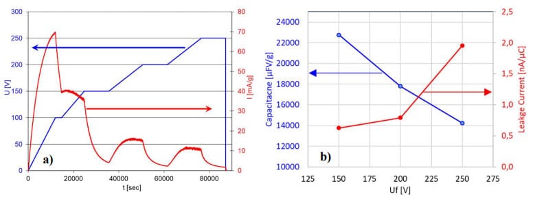
The term “constant rate anodization” refers to the way of anodization taking the loss of surface are during formation into account and continuously adjust the current required [16]. The red current curve in fig. 7a is automatically adjusted and correlates with the surface and capacitance loss with increasing voltage. Intermediate dwells at 100, 150 and 200 V reduce the temperature increase during forming and thereby decrease the breakdown probability.
After formation, all anodes were rinsed for 12 h in de-ionized water to remove all components of the electrolyte bath and were subsequently dried at 90°C. Several elements were then analyzed, the contents of oxygen (carrier gas reduced fusion), carbon (non-dispersive infrared adsorption following combustion in oxygen) and phosphorus (ICP-OES) as a function of forming voltage are presented in fig. 8. Please note, that all concentration data refer to weight. The sintered unformed anodes had a phosphorous content <20 ppm, 0,33 % oxygen and 33 ppm carbon.

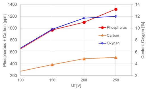
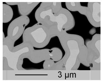
As a consequence of anodization, the oxygen content is increasing with increasing oxide thickness and therefore decreasing capacitance. It is known by several former publications that phosphorus is incorporated in the outer regions of the oxide film during anodization, probably as PO43- ions while the inner regions of the anodic Ta2O5 layer do not contain any phosphorus [6, 10-14]. However, a lot of these investigations have been only done on sputtered films under forming conditions not typically used today, i.e. mostly in water and not glycol-water solvent systems and mostly at lower voltages. The increased incorporation of phosphorus with increasing anodization voltage is in accordance to former findings. However, the phosphorus content of 970 ppm for anodes anodized to 150 V increases significantly to 1320 ppm for those anodized to 250 V. The incorporation of phosphorus is assumed to occur as phosphate. In accordance with literature [6, 10-14], we found a double layer oxide structure, i.e. a PO43- containing outer oxide layer and a presumably phosphate-free inner layer. This was detected in anodized HV200 anodes after polishing by using a special orientation contrast (in backscattering mode) with a FE-SEM (fig. 9). The darker scale of grey color corresponds to a lower relative atomic weight caused by the incorporated phosphate ions and the uniform appearance of this layer implies that this layer has a uniform PO43- distribution.

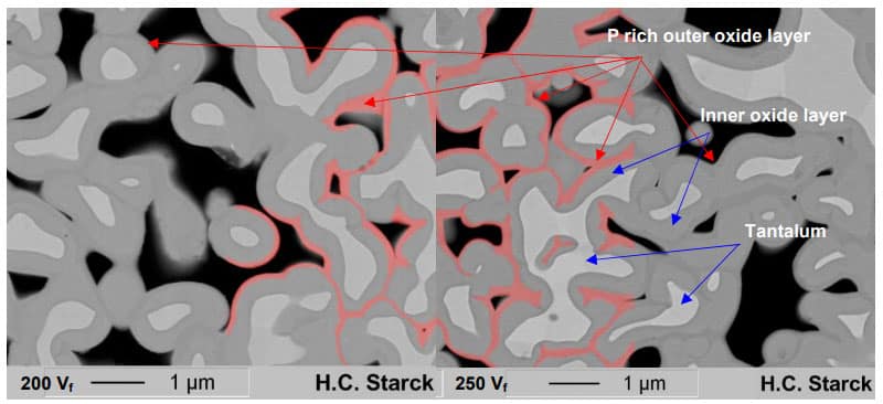
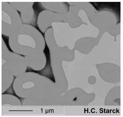
Anodization of similar anodes in glycol-water based solution using HNO3 to adjust to same conductivity of 900 µS/cm it could be shown that this is not an artifact of sample preparation. These anodes, shown in fig. 10, do not show any two-layer structure as observed for those anodized in H3PO4 before but the oxide film consists of only one layer as indicated by one scale of gray color using the same microscope adjustments.
The total oxide thickness of anodes made from HV200 powders anodized to 200Vf was determined to 370 nm, the outer phosphate rich layer being 85 nm. Shimizu et al. [10] investigated the incorporation of phosphorous into tantalum foils via SIMS depth profiling. They formed the foil at 25°C with a constant current up to 100 Vf. The total oxide layer thickness was about ~ 162 nm, while the P rich outer layer had a thickness of ~80 nm while in the following region between 80 to 110 nm the phosphorus content decreases constantly until zero level. Our anodes made from HV200 powders show a thinner outer layer which might be a result of totally different formation conditions: higher anodization temperature (60°C vs. 25°C), different anodization program (constant rate vs. constant current) and different size and shape of specimen (anode with nodular structure vs. foil).
The phosphorus content of 1100 ppm observed for anodes anodized to 200 Vs is corresponding to 3370 ppm Phosphate while the oxide content of 117000 ppm is corresponding to 637280 ppm Ta2O5 (oxide content of phosphate was already excluded in this calculation). This means that the total phosphate content of the oxide layer is 0.53 % what might be enough to have a negative impact on the breakdown stability under the assumption the phosphate weakens the amorphous oxide structure. But it must be further considered that only the outer area comprises the phosphate. This means, that the phosphorus content in the outer layer is according to the ratio of the layer thicknesses (85 nm of 370 nm) as high as 2,3 wt.-%. Taking the large difference of the molar weights into account (441,9 g/mol for Ta2O5 to 95,0 g/mol for PO43-) this is equal to 9,9 mol% phosphate. On the other hand, it is still an open question if this double layer structure created during anodization in phosphoric acid is beneficial or detrimental at very high formation voltages. Anodes anodized to 250 V and higher (fig. 11) show at some places non-destructive defects (these anodes had good leakage current!), which means that these anodes suffered no breakdown during anodization: cavities and holes have formed exactly at the interface between the outer phosphorus-rich and the pure Ta2O5 inner layer. These pores could contain gas (e.g., oxygen formed during anodization) or electrolyte or other unknown products of decomposition formed at high voltages. It will need further investigation to understand this observation. It should be mentioned that these defects were also found in anodes formed to these voltages made from standard Na reduced powders so that it can be excluded that the Mg reduction process used for the HVMC powder production is responsible for these cavities. The coincidence of the location of the cavities with the interface between the outer, phosphorus-rich oxide layer and the phosphorus-free inner oxide layer suggests that phosphorous may play a role for the formation of the cavities.


Surprisingly, a significant amount of carbon increase was also measured. Prior to anodization, the carbon levels were at 33ppm, but at 150 V, the anode has already picked up 390 ppm of carbon and towards 250V this is continuously increasing to 510 ppm. It is not known how carbon is incorporated into the anodic oxide film and how it is distributed but it is assumed that the main source might be the glycol that may decompose during anodization to these high voltages. In [15], it is mentioned that ethylene glycol-based electrolytes used for anodizing aluminum, must be almost totally esterified to be suitable for anodization voltages >400 Vf. Otherwise, oxidation products from free ethylene glycol like oxalic or formic acid will be generated and will attack the oxide film of the Al capacitor.
According to our own anodization experience, it is very hard or nearly impossible to form a Ta node to 150 V or even 250 V without breakdown or bad leakage current with powder carbon levels of > 60 ppm. However, the much higher carbon content after anodization did not result in an immediate breakdown during anodization or a bad leakage current in the case of anodes made from our HV200 powder. This implies that it is of great importance for the manufacturing of tantalum capacitors in which production step/and how carbon is “introduced”. Carbon rich areas in the powder (e.g., caused by insufficient debindering) could result in the local formation of tantalum carbide during sintering. Later, during anodization the carbide will cause oxide breakdown or crystallization. In contrast to that, the carbon that is, howsoever and as whatsoever compound incorporated during anodization seems to be less dangerous. However, the acceptable limit of C pick-up during anodization is unclear since surpassing a critical carbon level might be a reason for the increased leakage current observed at 250 V. The decomposition of forming electrolyte that contains organic components is a limiting factor for the realization of a new kind of Ta capacitor that is anodized to 400 V or higher. Oxide defects, as illustrated in fig. 10 could also be a consequence of the carbon pick-up (and interaction with PO43-?) during anodization. Further investigations are necessary to clarify the impact of bath temperature, electrolyte type and concentration but also of the anodization program and total forming time.
What should a perfect anodization concerning bath composition and forming program look like? Additives are needed that are stable during the whole formation process. The entrapment or incorporation of additives in which form whatsoever should be prevented so that a perfect oxide film can be generated, otherwise the breakdown strength might be reduced. Also, the thermal conduction of such electrolyte should be sufficient to dissipate the heat that is generated during anodization of large size anodes to high voltages.
Conclusion
We have presented the latest development of our HVMC high voltage tantalum powders that provide highest capacitance due to their improved microstructural homogeneity when compared to current standard powders. The newly developed HV150 powder provides a further capacitance increase up to 15 % at 150 Vf anodization by optimization of the primary particle and anode pore size structure. The primary pore peak is much narrower and higher compared to that of our HV100 and HV200 products. Moreover, the secondary pore peak is very close to the primary pore peak. Improved homogeneity is the key for future powder developments enabling even higher capacitance at high formation voltages.
The new pressing method of perimetric compression differs from the known techniques, in that it involves simultaneous compaction in both body axes orthogonal to the incorporated tantalum wire. Compared to conventional methods, the perimetrically compacted anode bodies are characterized by lower weight and dimensional tolerances, as well as less surface compaction (burnishing). In addition, this press can process both bindered and non-bindered powders avoiding the contamination with carbon.
We were successful in increasing the homogeneity in the primary pore and particle size distributions by adjusting our high voltage powder manufacturing process, resulting in our new HV400 powder. This powder extends the anodization range for tantalum powders from currently 300 V to 400 V, and allowing manufacturers to store even more energy in a given size. However, we found that the anodization process must be adapted as well. We have shown that not only phosphorous, which was already known, but also carbon is incorporated significantly into the formed anodic oxide film. Both components are introduced by the used electrolyte system. In contrast to former investigations reported in literature, this was to our knowledge the first time that such investigations on phosphorus contents of high voltage anodes with nodular structure anodized under typical high voltage up to 250 Vf conditions are reported. Nevertheless, finding a “perfect” anodization program in combination with a “perfect” anodization bath preventing the incorporation of critical amounts of foreign ions, remains a task to be followed up in the future.
References
[1] G. E. Moore “Cramming more components onto integrated circuits”. Electronics. Band 38, Nr. 8, 1965, 114–117
[2] M. Hagymási, H. Haas, C. Schnitter, H. Brumm, ”High Voltage Tantalum Powder – Challenges and Opportunities for new Powder Generation”, CARTS Europe, Nice, France 2011 CARTS Nice .
[3] M. Hagymási, C. Schnitter, R. Reifenheiser, O. Thomas, “Highest capacitance at higher voltages: Pushing the limits of tantalum high voltage capacitors” 2nd SPCD, Noordwijk, Netherlands 2016.
[4] Donald H. Stephenson, Martin D. Cymerman, Barry C. Muffoletto, “Using aqueous electrolyte containing ethylene glycol or polyoxyethylene glycol and phosphoric acid”, US6231993 B1, 29. Sept. 1999
[5] D. M. Smyth, T. B. Tripp, G. A. Shirn, “The Heat‐Treatment of Anodic Oxide Films on Tantalum IV. Anodization in Phosphoric Acid Solutions”, J. Electrochem. Soc. 1966 Vol. 113, issue 2, 100-104
[6] Q. Lua, S. Matoa, P. Skeldona, G.E. Thompsona, D. Mashederb, H. Habazakic, K. Shimizu, “Anodic film growth on tantalum in dilute phosphoric acid solution at 20 and 85 °C”, Electrochimica Acta, Vol. 47, Issue 17, 2002, p. 2761–2767.
[7] Herman A. Johansena, George B. Adams Jr., Pierre Van Rysselbergheb, “Anodic Oxidation of Aluminum, Chromium, Hafnium, Niobium, Tantalum, Titanium, Vanadium, and Zirconium at Very Low Current Densities”, J. Electrochem. Soc. 1957 Vol. 104, issue 6, 339-346
[8] M. Fernández, J. Baonza, J. M. Albella and J. M. Martínez-Duart, “Influence of electrolytes in the electrical characteristics of anodic films on tantalum“, Electrocomponent Science and Technology, 1981, Vol. 7, pp. 205-210
[9] D. Gerstemberg, “Handbook of Thin Film Technology”, chapter 19, Ed. L. I. Maissel and R. Glang, McGraw-Hill, N.Y. (1970).
[10] K. Shimizu, K. Kobayashi, G. E. Thompson, P. Skeldon, G. C. Wood, “Anodic oxide films on tantalum: incorporation and mobilities of electrolyte-derived species “, Philosophical Magazine B, 1996, Vol 73, N0.3, 461-485
[11] I. Montero, J. M. Albella, J.M. Martinez-Durat, L. Soriano, „Dielectric and Structural characteristics of Ta2O5 anodic films formed in phosphoric acid electrolytes “, J. of Materials Science “” (1987), 1785-1789
[12] C.J. Dell’Oca, L. Young, “Ellipsometric studies of anodic oxide films formed on tantalum in diluted phosphoric acid”, J. Electrochem. Soc., Vol. 117 (12), 1970, 1545-1547
[13] G. Amsel, C. Cherki, G. Feuillade, J.P. Nadai, “The influence of the electrolyte on composition of anodic oxide films’ on tantalum”. J. Phys. Chem. Solids, Vol. 30, 1969, 2117-2134
[14] K. Shimizu, G.M. Brown, H. Habazaki, K. Kobayashi, P. Skeldon, G.E. Thompson, G.C. Wood, “Direct observation of anodic films formed on tantalum in concentrated phosphoric and sulfuric acid solution”, Corrosion Science, Vol. 40, No. 6, 1998, 963-973
[15] J. T. Kinard, B. J. Melody, D. A. Wheeler, P. M. Lessner, “Method and electrolyte for anodizing valve metals to high voltages”, Patent US 6,346,185 B1, Feb. 12, 2002
[16] Marcel Hagymási, Ralph Dietmar Otterstedt, Christoph Schnitter, Oliver Thomas, Rich Reifenheiser, “Pushing Tantalum capacitors to the limit: A powder manufacturers view to 300 V anodizations and beyond.”, 3rd Space Passive Component Days (SPCD), International Symposium, Oct. 2018

