
This article, part of the Fuse Fundamentals series, has been prepared for the EPCI Knowledge Blog with cooperation and permission from Littelfuse. You can download the PDF version of the Fuse Fundamentals from Littelfuse’s website here. This comprehensive fuse selection guide will help you to understand which fuse is best for your application.
This article focuses on low-voltage AC power distribution, motor circuits, and semiconductor drives, primarily in installations that follow NEC and UL practices (e.g. North American industrial panels and switchgear). The selection principles, however, are general and can be mapped to IEC / EN fuse systems used in European and international applications. For fuse construction, performance and standardization details, see the related articles in the Fuse Fundamentals series: Fuse Characteristics and Features, Fuse Classes and Standards, and Primary Fuse Protection Against Overvoltage Events.
Key Takeaways
- This article provides comprehensive Fuse Selection Guidelines for low-voltage AC power distribution and motor circuits.
- It emphasizes important factors like maximum system voltage, average current, and environmental conditions for fuse selection.
- The article discusses time-delay, fast-acting, and high-speed semiconductor fuses, highlighting their appropriate applications.
- Additionally, it covers crucial aspects of fuse block selection, including current rating, voltage rating, and mounting configuration.
- Lastly, it outlines the importance of selective coordination to enhance system reliability and equipment protection.
Electrical System Specifications and Fuse Selection
read the related article in the fuse fundaments series: Fuse Characteristics and Features
Some important considerations to determine the fuse size include:
- The maximum system voltage
- The average current expected
- The maximum continuous current expected
- Whether the overcurrent protective devices can tolerate an expected inrush while interrupting true overloads
- to determine this, look at the expected inrush values on a fuse’s time-current curves
- Any special environmental considerations, such as dust, humidity, or very high or low temperatures. In demanding environments, consult your fuse supplier’s derating and application guidelines.
- The maximum available short-circuit current that the fuse may have to interrupt
When you select a fuse based on the above considerations, you will optimize your system’s safety, reliability, and performance.
Fast-Acting Fuses, High-Speed Semiconductor Fuses, and Time-Delay Fuses
Fuses must interrupt overloaded conductors and equipment before any overheating occurs. However, fuses should not interrupt temporary overloads.To provide sufficient overload protection for system conductors, UL established maximum fuse opening times at 135% and 200% of a fuse’s current rating.All UL Listed fuses in accordance with the NEC must meet these limits whether they are fast-acting fuses or time-delay fuses.
Because fuses are designed to respond to two types of overcurrents—short circuits and overloads—you must determine whether to use a time-delay fuse or a fast-acting fuse for the given application.
Time-Delay (SLO-BLO®) Fuses
Time-delay fuses offer the most comprehensive protection for both motor and general-purpose circuits by mitigating nuisance fuse openings and reducing the frequency of downtime incidents.
Many UL Class CC, CD, G, J, L, RK5, and RK1 fuses, along with some miscellaneous UL Listed fuses, are time-delay. To identify time-delay fuses, look for terms like “time-delay,” “T-D,” “D,” or similar markings on the label.
The minimum-time delay requirements differ among fuse classes. UL standards specify that Class J, Class RK5, and Class RK1 fuses must carry 500% of their rated current for a minimum of 10 seconds.
UL standards also require Class CC, Class CD, and Class G fuses to carry 200% of their rated current for a minimum of 12 seconds.
Although there’s no UL Classification for time-delay Class L fuses, they can still be labeled as “time-delay.” The manufacturer determines the duration of the time delay.
In addition to providing time delay for surges and quick overloads, time-delay fuses comply with all UL requirements for sustained overload protection. On higher current values, time-delay fuses function as current-limiting devices, effectively removing substantial overcurrents within less than half an electrical cycle (8.33 ms).
Compared to fast-acting fuses, time-delay fuses often have a rating that closely resembles the circuit’s operating current. For instance, Class RK5 and RK1 fuses can be rated from 125% to 150% of a motor’s full load current on most motor circuits. This offers excellent overload and short circuit protection, often allowing the use of smaller and less expensive disconnect switches.
Time-delay fuses have gradually replaced most one-time (UL Class K5) and renewable (UL Class H) fuses. Today, the majority of fuses sold by electrical distributors are time-delay fuses.
Dual-Element Fuses
Dual-element fuses are a sub-category of time-delay fuses.
Fuses with dual-element construction feature separate short circuit and overload elements. The time-delay elements are designed for overload protection, while the fast-acting fuse elements provide current-limiting short-circuit protection – see Figure 1. below.
Fast-Acting Fuses
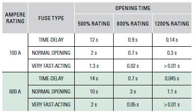
Fast-acting fuses lack an intentional time-delay feature. Their typical opening times at 500% of the fuse’s current rating range from 0.05 seconds to approximately 2 seconds. Fast-acting fuses are suitable for non-inductive loads, such as incandescent lighting and general-purpose feeders, or for branch circuits with minimal or no motor load.
When safeguarding motors and other inductive loads, fast-acting fuses must be rated at 200% to 300% of the load currents to prevent nuisance opening during inrush currents. However, these fuses lack sufficient protection against overloads and only offer short-circuit protection. Consequently, when employing fast-acting fuses to protect motors or inductive loads, it’s crucial to install overload relays or other overload protection devices to effectively safeguard the conductors and equipment from overload conditions.
High-Speed Semiconductor Fuses (Very Fast-Acting Fuses)
High-speed semiconductor fuses, also known as very fast-acting fuses, high-speed fuses, or ultra-rapid fuses, are designed for specific applications. They protect sensitive equipment, such as semiconductors found in variable frequency drives, inverters, power supplies, and rectifiers.
High-speed semiconductor fuses possess unique characteristics that safeguard components from line surges, low-value overloads, and short-circuit currents. They are highly current-limiting and respond swiftly to overloads and short circuits.
Application Fuse Selection Guideline
| Application / load type | Recommended fuse behaviour | Typical current rating guideline | Coordination / notes |
|---|---|---|---|
| Induction motors, pumps, compressors | Time‑delay (dual‑element) | 125–150% of motor full‑load current for RK1/RK5 classes | Good overload and short‑circuit protection, easier selective coordination with upstream fuses. |
| Motors with very high inrush or frequent starts | Time‑delay with long delay characteristic | Up to upper end of 150% range as required by inrush | Check time‑current curves to avoid nuisance opening during start; verify conductor protection. |
| Non‑inductive loads (incandescent, heaters, feeders with little motor content) | Fast‑acting | Close to circuit operating current for non‑inductive loads | Provides fast fault clearing; separate overload protection may not be needed for purely resistive loads. |
| Motors or inductive loads protected by external overload relays only | Fast‑acting + external overload relays | 200–300% of motor full‑load current | Fuse provides mainly short‑circuit protection; overload relay must protect conductors and equipment. |
| Semiconductor drives, inverters, rectifiers | High‑speed semiconductor | Per manufacturer application guide and I²t coordination | Highly current‑limiting, sized to protect semiconductor I²t and withstand line surges. |
| Control circuits, instrumentation | Fast‑acting low‑current or midget fuses | Slightly above maximum normal load current | Emphasis on protecting small conductors and sensitive components from faults. |
Fuse Block Selection Considerations
When selecting a fuse block (also known as a fuse holder) for a particular application, it’s crucial to choose the appropriate size based on the circuit’s requirements. Fuse blocks are available in various configurations, and the selection process involves considering several factors:
- Current rating: The maximum current the fuse block can handle.
- Voltage rating: The maximum voltage the fuse block can withstand.
- Interrupting rating: The ability of the fuse block to interrupt a current flow.
- Physical size: The dimensions and shape of the fuse block.
- Indication: The visual signal provided by the fuse block to indicate an overload.
- Number of poles: The number of connections the fuse block has.
- Mounting configuration: The way the fuse block is attached to the circuit.
- Connector type (wire termination): The type of connector used to connect the wires to the fuse block.
- Number of poles: The number of poles for each set of fuses.
The number of poles for each set of fuses is determined by the circuit’s characteristics. Most fuse block series are available in 1-pole, 2-pole, 3-pole, and 4-pole configurations. Some families offer the option to gang individual fuse blocks together, which may be limited by available panel space and the type of wire in use.
Mounting Configuration
Depending on the fuse block design, you should also consider how the fuse block is mounted or inserted into the panel.Historically, fuse blocks screwed into the back of the panel, but many newer designs have a DIN-rail mounting capability.The DIN-rail mounting feature allows the blocks to be quickly installed and removed from the rails.
Connector Type
There are three standard connector types (also known as wire terminations) with its fuse blocks:
- Screw: for use with spade lugs and ring terminals
- Screw with pressure plate: for use with solid wire and stranded wire without terminal, and recommended for applications where vibration will be a factor
- Box lug: the most durable of the three options and used with all types of solid wire, and Class-B and Class-C stranded wire.
Understanding Time-Current Curves and Peak Let-Through Curves
The performance capabilities of various fuses are represented by two different types of fuse-characteristic curves: time-current curves and peak let-through curves.
These define the operating characteristics of a given fuse, which is essential in selecting the most suitable fuse for your application’s needs.
Note on IEC / EN fuse systems
While the examples in this article use UL fuse classes (e.g. RK1, J, L) and NEC terminology, the same time‑current and current‑limiting principles apply to IEC / EN fuses. General‑purpose gG/gL fuses correspond broadly to time‑delay, current‑limiting power fuses, while aR fuses are fast semiconductor protection fuses focused on short‑circuit protection. For European installations, fuse selection should be made against IEC 60269 and local implementation (such as EN standards), using the same process: define system voltage and fault level, classify the load, then select appropriate fuse characteristics and verify curves and coordination.
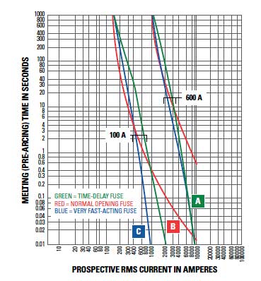
Time-Current Curves
Time-current curves (see Figure 2) show a fuse’s average melting (opening) time at any current.To make the curves more readable, the performance information is presented on a logarithmic plot.
Time-delay fuses, fast-acting fuses, and high-speed semiconductor fuses all respond differently based on the overcurrent. Figure 2 compares the average melting times for 100-ampere and 600-ampere ratings of three fuse types:
- Littelfuse dual-element time-delay LLSRK series class RK1 fuses (see Figure 2(A))
- Littelfuse normal-opening NLS series class K5 fuses (see Figure 2(B))
- Littelfuse L60S series high-speed fuses (see Figure 2(C))
To further illustrate this point, Table 1 compares the opening times for each of these fuses.
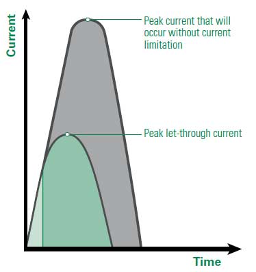
Peak Let-Through Curves
Peak let-through curves show the maximum instantaneous current through the fuse during the total clearing time.This represents the fuse’s current-limiting ability. Current-limiting fuses open severe short circuits within the first half-cycle (180 electrical degrees, which is equal to about 8.33 ms) after the fault occurs. Current-limiting fuses also reduce the peak current of the available short-circuit current to a value that is less than what would occur without the fuse (refer to the Current-limiting effect of fuses diagram on page 8).
Peak let-through curves (see Figure 4) show a fuse’s current-limiting effects.
Peak Let-Through Curve Example
To better understand the function of these curves, let’s illustrate with an example.
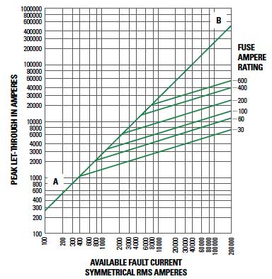
Begin at 100,000 rms symmetrical amperes (refer to Figure 3) and read upward along the A–B line. From this point, move horizontally to the left and read the instantaneous peak let-through current of 230,000 A.
In a typical circuit with a 15% short-circuit power factor, the instantaneous peak of the available current is approximately 2.3 times the rms symmetrical value. This occurs because the A–B line has a slope of 2.3:1.
The diagonal curves that branch off the A–B line represent the current-limiting effects of various fuse current ratings for a specific fuse series.
Now, let’s examine another example. Begin by reading the bottom of Figure 3 at 100,000 rms symmetrical amperes and read upward until you reach the intersection of the 200-ampere fuse curve. From this point, move horizontally to the left and read the peak let-through current of approximately 20,000 A.
This information indicates that the 200-ampere fuse reduced the peak current during the fault from 230,000 A to 20,000 A. This is the current-limiting effect of the 200-ampere fuse, and 20,000 amperes is less than one-tenth of the available current.
This is crucial because the magnetic force generated by current flow is directly proportional to the square of the peak current.
If the peak let-through current of a current-limiting fuse is reduced to one-tenth of the available peak current, the magnetic force will be diminished to less than 0.001 of what would occur without the fuse.
Peak let-through curves are valuable tools in determining whether a fuse can effectively protect a specific piece of equipment.
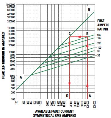
For instance, let’s say we have a 100,000 rms symmetrical ampere available fault-current and want to determine if 600-ampere 250-volt time-delay Class RK1 fuses can adequately protect equipment with a 22,000-ampere short-circuit rating (as depicted in Figure 4). Here’s the step-by-step process:
- Begin by locating the 100,000-ampere available fault-current on the bottom of the chart (Figure 4(A)). Then, follow this value upward until it intersects with the 600-ampere fuse curve (Figure 4(B)).
- From this intersection point, move horizontally to the left until it intersects with the A-B line (Figure 4(C)).
- Read down to the bottom of the chart (Figure 4(D)) to find a value of approximately 18,000 A.
Therefore, the POWR-PRO® LLNRK 600-ampere RK1 current-limiting fuses are suitable for this application. These fuses effectively reduce the 100,000-ampere available current to an apparent or equivalent 18,000 A. Consequently, equipment with a short-circuit rating of 22,000 A can be safely connected to a system with a 100,000 available rms symmetrical amperes.
The up-over-and-down method can also be employed to provide backup short-circuit protection for large air power circuit breakers. Additionally, it allows the installation of non-interrupting equipment (such as bus ducts) in systems with available short-circuit currents (known as prospective currents by IEC) that exceed their short-circuit (withstand) ratings.
However, it’s important to note that this method should not be used to select fuses for the backup protection of molded case or intermediate frame circuit breakers. NEC Article 240.86—Overcurrent Protection, Series Ratings—requires series ratings and states that when a circuit breaker is used on a circuit with an available fault current higher than the marked interrupting rating by being connected on the load side of an approved overcurrent protective device with a higher rating, the circuit breaker must meet the requirements specified in 240.86 (A), (B), or (C).
UL-listed fuse-to-circuit breaker series ratings are readily available from most load center and panelboard manufacturers. Additionally, many local builders also provide these ratings.
The NEC mandates that industrial control panels be labeled with their short-circuit current rating. These labels facilitate comparisons between the equipment’s short-circuit current rating and the available short-circuit current, thereby preventing potential hazards.
Selective Coordination
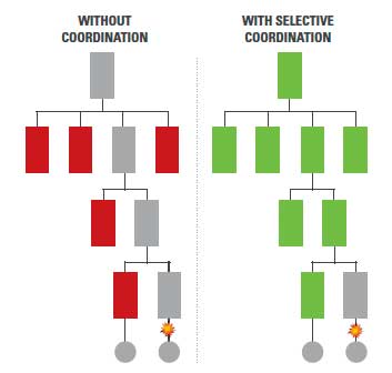
Selective coordination (Figure 5) involves coordinating overprotective devices’ time-current characteristics to ensure that when an overcurrent occurs, only the closest upstream device on the line side of the problem opens. This approach minimizes the impact on the entire electrical system, reduces the number of equipment removed from service, facilitates the easy identification of the overloaded circuit, and minimizes the time required to restore full-service operations.
Fuse Selectivity
For a system to be considered coordinated, the smaller fuse total clearing I2t must be less than the larger fuse melting I2t. In other words, if the downstream (branch) fuse opens the circuit before the overcurrent affects the upstream (feeder) fuse element, the system is selectively coordinated. This can be determined by analyzing curves that show melting and total clearing I2t, or from minimum melting and maximum clearing time-current curves.
However, the simplest method for coordinating low-voltage fuses is by using a fuse coordination table (Table 2). This table is specifically applicable to the Littelfuse POWR-PRO® and POWR-GARD® fuse series.
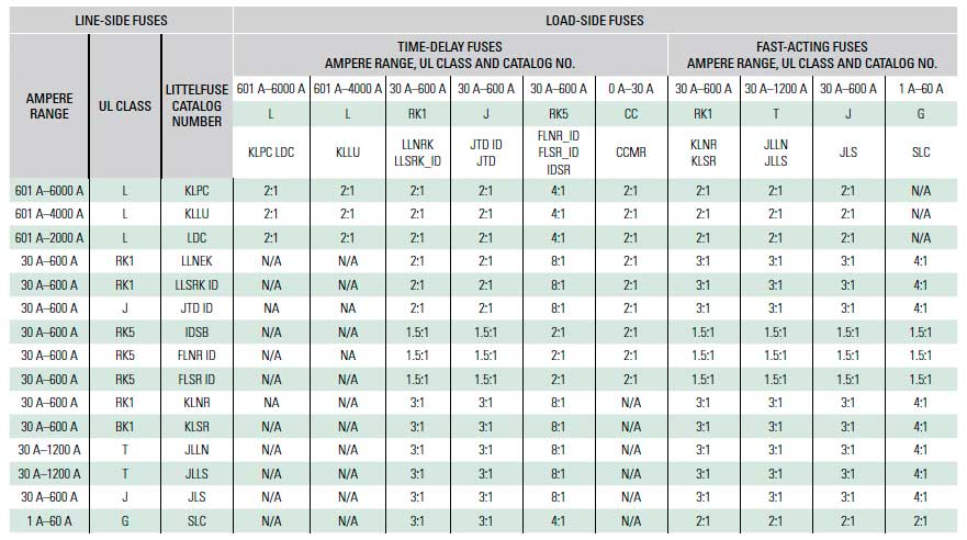
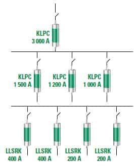
Fuse coordination tables significantly reduce design time. Equivalent fuse classes and performance are available from other major fuse manufacturers; the examples here use Littelfuse data for illustration. For instance, the coordination table indicates that POWR-PRO KLPC Class-L fuses coordinate at a 2:1 ratio with other Class-L fuses, with POWR-PRO LLNRK / LLSRK / LLSRK_ID series Class RK1 fuses, and POWR-PRO JTD / JTD_ID series Class J fuses. In the system depicted in Figure 6, the 3,000-ampere Class-L main fuses have at least twice the ratings of the 1,500-ampere, 1,200-ampere, and 1,000-ampere Class L feeder fuses. Utilizing this 2:1 ratio, we can confidently assume that these fuses will coordinate.
The coordination table also shows that the Littelfuse LLSRK_ID series time-delay RK1 feeder and branch circuit fuses coordinate at a 2:1 ratio with the Class L feeder fuses, so the entire system in Figure 6 can be considered completely coordinated.
Circuit-Breaker Coordination
As a result of the numerous types of circuit breakers and circuit breaker trip units available in the market, developing a coordinated circuit breaker system or coordinating circuit breakers with fuses is beyond the scope of this paper.
NEC Requirements for Selective Coordination
Component Short-Circuit Protecting Ability
The NEC requires equipment protection to be coordinated with overcurrent protective devices and for the available short-circuit current to prevent extensive damage to the equipment.This means that electrical equipment must be capable of withstanding heavy overcurrents without becoming damaged, or to be properly protected by overcurrent protective devices that will limit damage.When a severe fault occurs in an unprotected circuit, the current will immediately increase to a very high value.This is known as the available short-circuit current (or sometimes as the prospective fault current).
Current-limiting fuses respond so quickly to the increasing current that they interrupt the current within the first half-cycle—or before the current even reaches its first peak (see Figure 1.). Current-limiting fuses stop currents from damaging equipment faster than any other protective device.They also greatly reduce or even completely prevent component damage from high-fault currents. This performance capability helps people meet NEC Article 110.10 requirements and keep their systems safe.
Current-limiting fuses stop currents from damaging equipment faster than any other protective device
Practical Fuse Selection Workflow
This step-by-step workflow helps you select suitable fuses for low-voltage AC power distribution, motor circuits, and semiconductor drives in systems that follow NEC/UL practices, with principles that can also be mapped to IEC/EN installations.
By following these steps, you will select fuses that provide effective overload and short-circuit protection, minimize nuisance operation, coordinate with upstream and downstream devices, and comply with relevant safety and installation standards.
How to Select the Right Fuse for Your Application
- Define system basics
Identify the nominal system voltage and frequency, grounding scheme, and the maximum available short-circuit current at the point where the fuse will be installed.
- Classify the load type
Determine whether the load is a motor or transformer with inrush, a non-inductive or general-purpose load, or a semiconductor-based load such as a drive, inverter, rectifier, or power supply.
- Choose the appropriate fuse family
Select a time-delay fuse (often dual-element) for most motors and mixed loads, a fast-acting fuse for non-inductive or lightly inductive circuits, or a high-speed semiconductor fuse for power electronic equipment.
- Select voltage and interrupting ratings
Ensure the fuse voltage rating is equal to or greater than the system voltage, and that the interrupting rating is at least as high as the available short-circuit current at the installation point, following NEC/UL or IEC/EN requirements.
- Size the fuse current rating
For motor circuits, use typical guidelines such as 125–150% of motor full-load current for time-delay fuses, or 200–300% for fast-acting fuses used with external overload protection. For semiconductor fuses, follow manufacturer application curves and I²t recommendations.
- Check time-current and let-through performance
Use time-current curves to verify that the fuse rides through expected inrush and temporary overloads while opening quickly enough on sustained faults. Use peak let-through curves and the “up-over-and-down” method to confirm that the fuse will limit fault current to a level that downstream equipment can safely withstand.
- Verify selective coordination
Compare the I²t or time-current characteristics of upstream and downstream fuses to ensure that the downstream device clears the fault first. Where available, apply manufacturer fuse coordination tables and recommended current ratios to achieve selective coordination.
- Select compatible fuse blocks and holders
Choose fuse blocks or holders that match the selected fuse class, voltage, current, and interrupting rating, and that provide suitable mounting (DIN-rail or panel), number of poles, indication features, and connector type for the wiring method used.
- Consider environmental and installation factors
Account for ambient temperature, enclosure type, ventilation, and contamination such as dust or humidity. Apply any derating or special recommendations provided by the fuse manufacturer for demanding environments.
Conclusion
Correct fuse selection is a key part of designing safe, reliable and code-compliant power distribution, motor circuits and semiconductor drive systems. By starting from system requirements, load type and fault levels, and then using time-current and peak let-through curves, engineers can choose fuses that both protect equipment and avoid nuisance operation.
Time-delay, fast-acting and high-speed semiconductor fuses each have their own strengths, and must be coordinated with upstream and downstream protection, as well as with suitable fuse blocks and holders. Applying the workflow and guidelines in this article helps ensure proper overcurrent protection, selective coordination and long-term system performance.
Fuse Selection FAQ
The main goal of fuse selection is to protect conductors and equipment against overloads and short circuits while avoiding nuisance openings during normal inrush or temporary overloads. Correctly selected fuses improve safety, reliability, and compliance with NEC, UL, and IEC/EN requirements.
Key parameters include system voltage, frequency, maximum continuous and expected inrush current, available short-circuit current at the installation point, load type (motor, non-inductive, or semiconductor), and environmental conditions such as ambient temperature and humidity.
Time-delay fuses can carry temporary overloads and motor inrush without opening, while still interrupting sustained overloads and short circuits. Fast-acting fuses respond quickly to overcurrent and are suitable for non-inductive loads or circuits with little inrush, but usually need higher current ratings on inductive loads to avoid nuisance operation.
High-speed semiconductor fuses are used to protect sensitive power electronics, such as variable frequency drives, inverters, rectifiers, and power supplies. They are highly current-limiting and are selected so that their I²t characteristics protect semiconductor devices from line surges, low-value overloads, and severe short circuits.
For most motor circuits, time-delay fuses are typically sized at about 125–150% of motor full-load current, while fast-acting fuses used with separate overload protection may be sized around 200–300% of full-load current to ride through starting inrush. Exact values should follow manufacturer data and applicable codes.
Selective coordination means that only the protective device closest to a fault opens, while upstream devices remain closed. This minimizes system downtime, simplifies fault location, and supports NEC requirements. Coordination is achieved by comparing time-current and I²t characteristics, or by using manufacturer coordination tables and recommended fuse current ratios.
Time-current curves show how quickly a fuse opens at different overcurrent levels, which is critical to avoid nuisance operation and to protect conductors and equipment. Peak let-through curves show the maximum instantaneous current during a fault, indicating how effectively a current-limiting fuse reduces the fault magnitude and associated mechanical and thermal stress.
Fuse blocks must match the fuse voltage, current, and interrupting rating, and provide the correct number of poles, mounting method (DIN-rail or panel), indication features, and connector type (screw, screw with pressure plate, or box lug). Mechanical robustness and wiring method also influence the final choice.
References and Further Reading
Fuse Fundamentals series on Passive Components Blog
- Fuse Characteristics and Features – overview of time-current behaviour, current limitation, temperature effects and key fuse performance parameters.
- Fuse Classes and Standards – description of UL and IEC fuse classes, markings and standard requirements for low-voltage power and semiconductor fuses.
- How Fuses and Circuit Breakers Work Based on Critical I²t – explanation of I²t concepts, energy let-through and coordination between fuses and circuit breakers.
- ABC of Fuses – article collection – index of fuse-related knowledge articles, including primary fuse protection, selection guidelines and application notes.

