
Bourns Inc. published its application note guidelines about selection of the right transformer for high voltage energy storage applications. The application note explains some basic guidelines and point to reinforced construction of some Bourns specific series, nevertheless the guidelines can be use as a general recommendation to consider for high voltage transformer selection in energy storage applications.
Introduction
Providing isolated low voltage bias power to ICs such as microcontrollers, analog-to-digital converters, isolated gate drivers or voltage monitoring ICs in high voltage systems is usually accomplished with an isolated DC-DC converter. If the high voltage system is spread out over several modules, the architecture may call for a parallel DC bus on the low voltage side with multiple isolated low power DC-DC converters for each module.
Because it is used multiple times in this scenario, an efficient and cost-effective topology is the best approach. This application note highlights the design benefits of using push-pull transformers that are proven solutions for these situations. Used as an example is the Bourns® Model HCTSM8 series transformer, which is AEC-Q200 compliant and available with a wide range of turns ratios as standard.
Multiple turns ratios are an important feature enabling the same basic circuit topology to be replicated across a system with the same components and PCB layout. With a transformer series like the Model HCTSM8, designers are able to select the right reinforced transformer part number based on the specified output voltage for powering a microcontroller or an isolated IGBT gate driver.
Why Push-Pull Transformers are an Optimal Choice
Electrical Advantages
Push-pull transformers are known to operate well with low voltages and low variations in input and output. This characteristic is ideal for a microcontroller bias or gate driver IC that has constant power levels and input voltages. Unlike typical flyback and forward topologies, the push-pull topology offers high efficiency at a stable input and output current. Any variations in input and output current tend to waste energy as the power dissipated in the switches remains constant.
In addition, flyback transformers can cause EMI problems and often require closed loop control for stable operation even though they can efficiently handle wide input ranges. Conversely, a pushpull transformer can operate very simply in open loop. Compared to the number of components required for closed loop control, open loop control only requires a combination of a driver with a fixed duty cycle along with two MOSFETs, a transformer whose turns ratio is selected to suit the desired output, two Schottky diodes, and two ceramic capacitors.
In fact, the driver can be a microcontroller that may already be in use. If a microcontroller is used as the driver, then additional NPN transistors and resistors are necessary to provide the gate drive of the push-pull MOSFETs.
There are other reasons that justify the choice of a push-pull transformer. The shape of the output current is regular and not pulsating, which tends to stress the diodes and capacitors. For a relatively low current solution, diodes offer a cost-effective addition that can help ensure compensation and balancing of the transformer.
If the magnetizing current is imbalanced, the additional current in the winding will cause the drain-to-source resistance of the driver MOSFET to increase. This increases the voltage drop across the MOSFET and reduces the voltage across the winding, thereby equalizing the imbalance.

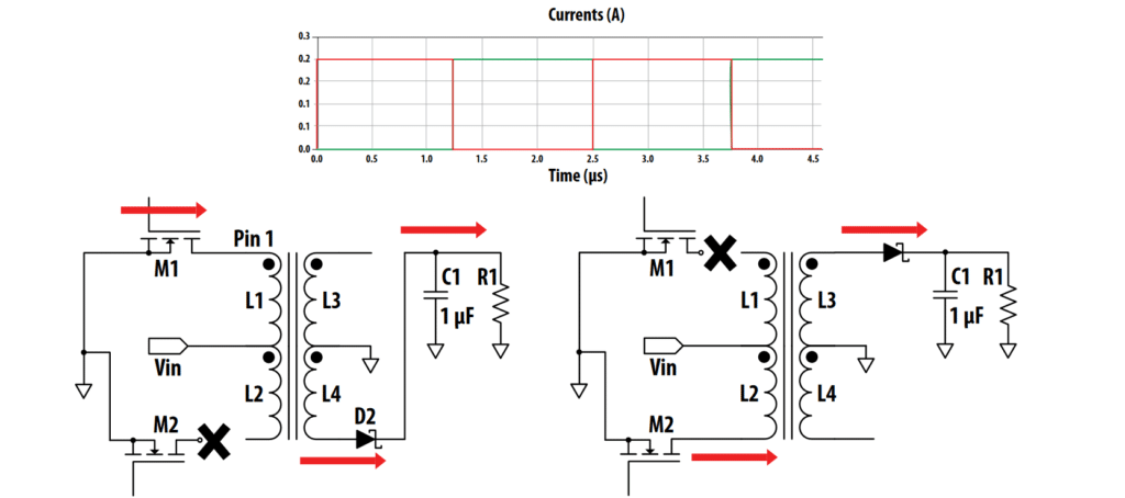
green lines indicating output current
Mechanical Benefits
Space-Saving
Specifying a push-pull transformer for low voltage applications offers several space-saving benefits. They typically are offered in a smaller footprint than flyback transformers. And because push-pull transformers are designed as “pure” transformers, they usually have physically smaller ferrite cores compared to flyback transformers.
Plus, there is no gap required in the ferrite core of a push-pull transformer, and, therefore, the effective permeability remains high and the magnetizing inductance can be quite high for a low number of turns. Given a sufficiently high switching frequency and low DC voltages, the flux generated (Volt Seconds per Turn) remains well below the saturation point.
Contrast this result with the split ferrite core in a flyback transformer where more turns are needed to ensure the current does not saturate the transformer. If there are tight space considerations and restrictions, the DC resistance will inevitably increase with the higher number of turns, resulting in reduced efficiency.

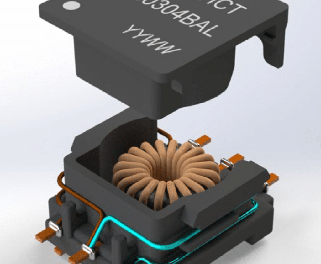
It is advised to look for a push-pull transformer with a toroidal core. What makes them a good choice is that there is no need for a gap, and a toroidal core is well known for providing good coupling between windings. This is because the flux has a short distance to travel and there is little dispersion between windings.
The relatively high inductance factor of a push-pull transformer with a toroidal core means it is possible to achieve high magnetizing inductances without a high number of turns. Plus, a coil former is not required as the wires are wound directly on the ferrite, which feature a high dielectric protective coating.
Coil formers add extra space as does the fact that the ferrite split core is exposed on the top and bottom if the transformer is an SMD device. A toroid core can be enclosed in a housing separating the core from the circuit board.
This difference automatically minimizes the footprint on a PCB in high voltage applications where safety distances (creepage and clearance) are required as defined by the standards for insulation (IEC 60664) and communications equipment (IEC 62368) that mandate a specified distance between the high voltage hazardous side of the PCB and the low voltage side. If the core is exposed, the clearance will be significantly reduced which will need to be compensated by additional width or height of the plastic carrier.
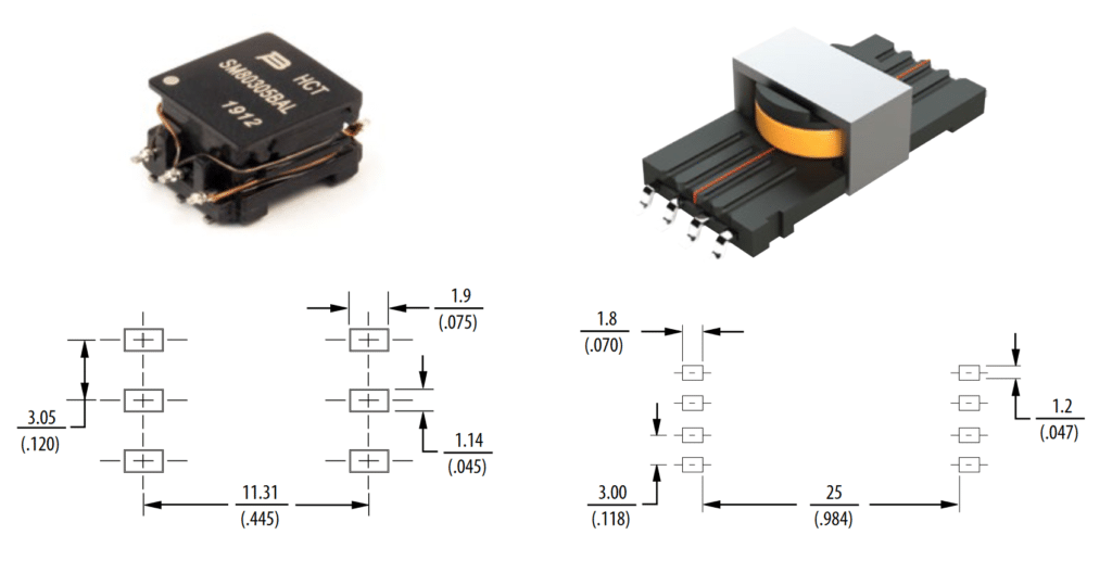
Figure 2 shows a comparison in terms of dimensions between the Bourns® Model HCTSM8 transformer and a transformer with a split core such as an E13. The figure illustrates that the E13 solution requires 90 percent more room on the PCB in order to meet the same isolation level of the Bourns® HCT transformer. Furthermore, the leakage inductance of a transformer with an extended bobbin needs at least 200 percent more space on the PCB compared to a transformer with a tightly coupled toroid, even with the primary wrapped around the outside of the housing.
Better Insulation

The Bourns® Model HCTSM8 has reinforced insulation, which according to standards must consist of either triple insulated wire (three separate layers of insulation on the wire) on one winding or insulation on both windings (double insulation).
Double insulation is not efficient from an electrical point of view. The time to strip the insulation from the start of the coil during the winding process will be twice that of a triple insulated transformer. The effective space for conductors is reduced in a double insulated system as both coils have at least 0.08 mm of insulation compared to 0.02 mm for pure magnet wire with enamel.
The time required to wind a toroid with insulated wire is higher compared to enamel coated wire. Therefore, double insulation is less efficient and more expensive. However, to some customers double insulation has the advantage of offering real redundant insulation compared with triple insulated wire.
Using the HCTSM8 series transformer example, the secondary winding consists of FIW (fully insulated wire), which is considered as strong as triple insulated wire but without safety agency recognition (for many types). This is particularly relevant in a transformer with a toroidal core. The concern is the effect of triple insulated wire which could degrade and cause a short to the core and also from the core to the non-insulated wire. This risk can be mitigated using FIW wire on the secondary side.
Maximum Creepage/Clearance
The Bourns® HCTSM8 push-pull transformer makes full use of the enclosure around the ferrite core to maximize creepage and minimize the footprint. The core is not visible from the pins of the design so the clearance pin to core will be measured up the wall of the device and down the joint between the lid and the side wall.
The effective tracking distance over the insulated wire from pin to core is maximized by running the insulated wire around the outside of the component. By using this breakthrough design that features a press fit of the lid against side wall and the wraparound insulated wire, the Model HCTSM8 series can obtain a creepage and clearance of 8.0 mm despite having a nominal height of just 6.5 mm and a distance from pad to pad on the PCB of 11 mm max.
In addition, the Model HCTSM8 uses plastic material classified as Class I, which means it is the least conductive of all plastics to high voltages. It features triple insulated wire on one winding (primary). Consequently, by taking 8.0 mm as creepage and clearance distance and consulting table F.4 of IEC 60664, this transformer offers a working voltage of 800 Vrms.
As a result, inverters and battery packs with rms voltages of up to 800 Vrms requiring reinforced insulation could use the HCTSM8 for the following two energy storage applications:
- A) Isolated DC voltages for a gate driver for an IGBT or SiC MOSFET
- B) Isolated DC power for a microcontroller or voltage monitoring IC or transceiver
Typical Application Usage
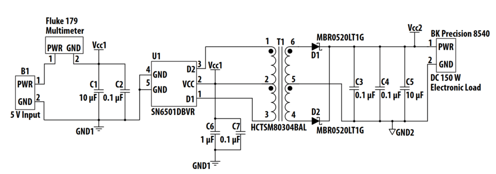
To generate plus and minus voltages for a gate driver, a circuit configuration similar to that shown in Figure 4 represents why Bourns® Model HCTSM8 is a valid solution.
In this example, the device is driven by an integrated Texas Instruments SN6501 push-pull driver. The Texas Instruments device operates at a high frequency (400 kHz) and has a fixed duty cycle (50 percent).
The output relationship in a push-pull driver with Input Vin and Output Vout and duty cycle D is as follows:
Vout = 2 x D x n x Vin , where n is the turns ratio from secondary to primary.
Model HCTSM8 has 11 different standard turns ratios. Because the Texas Instruments SN6501 device uses internal MOSFETs whose maximum voltage rating is 5 V, the Vin cannot exceed this level. And in order to generate 12 V which is required to switch on an IGBT, it requires a turns ratio of 2.5. It is not possible to push D beyond 50 percent in a push-pull transformer as the time to magnetize and demagnetize the core must be balanced or saturation will occur.
The negative voltage can also be generated from the same transformer by attaching a shunt reference between the ground rail and a negative output. Given that the Model HCTSM8 series is a catalog product with AEC-Q200 compliant quality levels, it provides an efficient and cost-effective isolated power source compared to a customized transformer. A customized solution typically requires multiple outputs involving soft tooling and hard tooling, as well as the additional costs to develop.


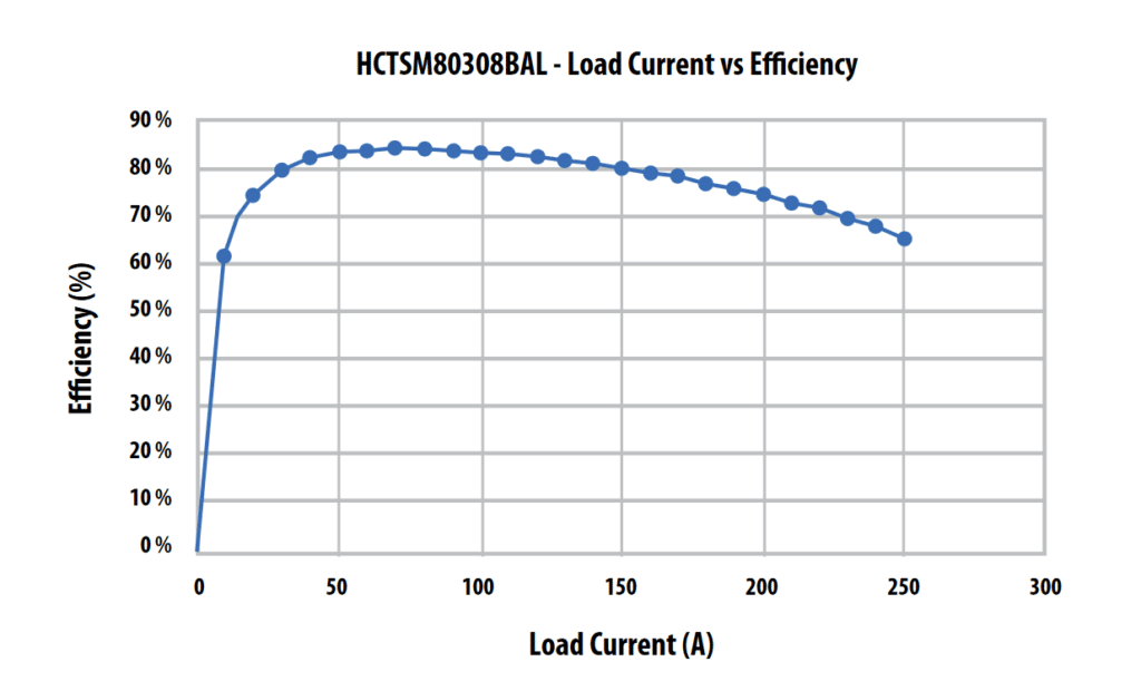
Figure 5 shows the efficiency of a circuit when using Model HCTSM80308BAL, which is an ideal solution to provide the 15 V needed for an isolated gate driver IC. The optimum operating point for this application is between 100 mA and 150 mA output current.
Figure 6 shows the test circuit used to validate the HCTSM8 series and highlights the test board and equipment used for calculating overall power efficiency.

BMS Transformer Safety Testing
The question of ensuring that the transformer’s insulation will remain intact from the tape in which it is delivered to the board and during the lifetime of the application is answered by complying with accepted industry standards.
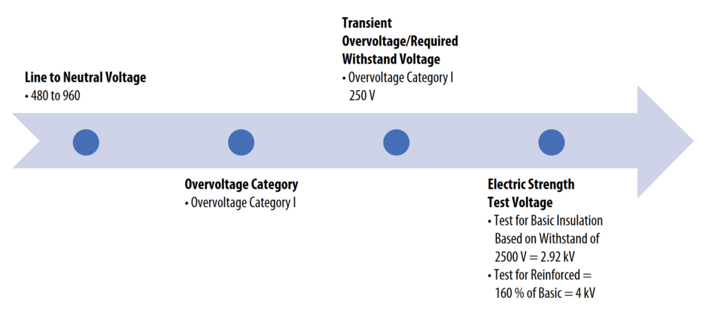
Bourns designed and tested its Model HCTSM8 series to survive identified solder reflow conditions and can be reflow soldered three times without degradation of the insulating wire. The insulation strength was tested using a Hi-POT tester applying 4 kV rms for up to 60 seconds. Shown in Figure 7 is the criteria Bourns used when it defined the electrical isolation specification:

Determining the Overvoltage Category depends on where the power supply is located. If there is no risk of a transient from the mains hitting the power supply, such as where the voltage source is located relative to the battery, then the application may be categorized as Category I. If there is an isolated connection to the mains supply, it is permitted to move from Category II to Category I.
The Hi-POT test is used to check the solid insulation in the transformer but it can also be used to verify that the clearances comply with the standard. Any signs of arcing or corona discharges will be a clear failure.
The Model HCTSM8 is designed for 800 Vrms at a 2000 m altitude. For higher altitudes, the working voltage must be derated as the breakdown voltage or corona of air decreases as the air becomes thinner.
Future Trends
Working voltages of 1000 V and 1500 V for transportation applications, as well as energy storage in industrial installations, require isolation testing with various levels of test voltages according to the relevant standards as shown in Figure 8.
The IEC 60664 standard also refers to using partial discharge testing to ensure there are no defects in the insulation such as tiny pinholes, which would expand over time under a strong electric field. In fact, complying with IEC 60664 requires that designs pass the standard of partial discharge if the electric field between primary and secondary exceeds 1000 V/mm and if the working voltage exceeds 750 V.


Design Advantages
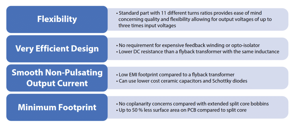
This application note illustrates the advantages designers can leverage by using the Bourns® HCTSM8 series transformers for module hardware energy storage applications. The flexibility, efficiencies, low EMI and space-saving benefits present a compelling solution for these designs.

The Bourns® HCT series has been tested and approved by Texas Instruments in their Model SN6501 and SN6505 series of push-pull drivers. As the range of applications for high voltage driven equipment in transportation and other markets increases, so too will the demand for stable, high quality and standardized isolated power designs in applications such as modules in high voltage battery or ultra-capacitor packs. Bourns offers 11 different fully tested and AEC-Q200 compliant Model HCTSM8 series push-pull transformer part numbers for the Texas Instrument drivers. Based on Bourns’ advanced power transformer design, the HCTSM8 series delivers the right combination of isolated power with low voltages for energy storage gate drivers, microcontrollers, battery management ICs and many more applications.

