

source: National Institute of R&D in Microelectronics (IRM) Bucharest Romania , ESA SPCD 2018 Symposium
EPCI e-symposium library article
This paper presents the progress in the development of monolithic integrated band pass filters, achieved in the frame of the ESA project No. 40000115202/15/NL/CBi (“Microwave filters based on GaN/Si SAW resonators, operating at frequencies above 5 GHz”). The main objective focused on the design, fabrication and characterization of compact band pass filters processed on a 1 µm thin epitaxial GaN layer, grown on a silicon substrate, operating at ~5 GHz. In order to achieve this goal, inter-digital transducers (IDT) with digit/interdigit widths below 200 nm were designed. Due to the high losses occurring in the case of transversal filters, an approach based on the use of multiple Surface Acoustic Wave Resonators (SAW-Rs) was developed.
published by EPCI under approval of ESA SPCD 2018 organizing committee.
Title: Recent developments in microwave filters based on GaN/Si SAW resonators, operating at frequencies above 5 GHz
Author(s): Alina-Cristina Bunea (1) , Dan Neculoiu (1) , Adrian Dinescu (1); Leo Arij Farhat (2)
Organisation(s): (1) National Institute of R&D in Microtechnologies (IMT) Bucharest, Romania
(2) ESTEC, ESA, Keperlaan 1, Noordwijk, The Netherlands
Symposium: ESA SPCD 2018
Reference: New Developments 1
ISBN: N/A
e-Sessions Applications: Telecommunication
e-Sessions Scope Components: Filters, RF passives, Inductors
e-Sessions Topics: Technology
I. INTRODUCTION
This approach requires an accurate control of the series and parallel resonance frequencies of the different SAW-Rs placed in series or in parallel with the signal path. Since it is difficult to tune the resonance frequencies by means of metallization thickness and/or digit/interdigit widths at the level of accuracy required by the filter design, the new approach uses printed inductors connected in series or in parallel with the SAW-R. At frequencies higher than 5 GHz, these inductors are in the 0.2 – 2 nH range and can be integrated monolithically into the SAW-R based filter structure, resulting in a very compact device.
Printed inductors connected in series and monolithically integrated with SAW-Rs with IDT digit/interdigit widths within the 130-200 nm range, operating in the 5.4 – 8.6 GHz frequency range, will be presented. It will be shown that series connected inductors with values between 0.2– 1 nH tune the series resonant frequency of the SAW-R with up to 0.75%. An effective coupling coefficient of 1% was measured for these structures. The temperature effect on the tuned SAW resonators was investigated and the temperature coefficient of frequency is about –40 ppm/K.
Because of the high influence on the performance of the filter, the effect of the technological dispersion on the response of SAW-Rs fabricated on GaN/Si is studied. SAW-R test structures with interdigital transducers having the digit/interdigit widths of 200 nm were processed on a quarter of a 3 inch wafer and the resonant frequency deviation as a function of the position on the wafer is analyzed. The effects on the resonance frequency of the variation of the GaN layer thickness, the metallization thickness, the electrode width and the variation of the elastic constants due to the thermal strain are extracted from COMSOL simulations and compared to the expected deviation of the resonant frequency based on structural characterization results (SEM, AFM, ellipsometry).
The SAW band pass filter design with SAW-Rs controlled by series and parallel connected inductors is presented. It consists of three SAW-Rs connected in a PI-type configuration. The filter is
optimized at circuit level, with a reasonable estimate of the mechanical, conductive and dielectric losses. The simulated insertion losses are about 10.4 dB at 5.5 GHz, the rejection is better than 40 dB at 5.42 GHz and 5.58 GHz. The 3 dB bandwidth is 8 MHz. The effect of a higher level of different losses on the transmission characteristics is also investigated.
II. SAW BAND PASS FILTER CONFIGURATIONS
Common SAW based band-pass filters (BPF) include: delay line type filters, longitudinally-coupled resonator filters and impedance element filters (ladder filters), schematically shown in Fig.1 (a), (b) and (c), respectively [1]. At ire connections are not reliable as a interconnect technology, the band pass filters require coplanar waveguide transmission line (CPW-TL) topologies.
With one metallic strip for the signal line and two large metallizations for the ground plane, the CPW-TL is the ideal choice for the microwave circuits that need both series and parallel connection of components without substrate vias [2].
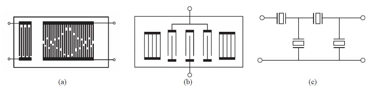

Fig.1. SAW based band-pass filters include: (a) delay line type filters; (b) longitudinally-coupled resonator filters; (c) impedance element filters (ladder filters)
The coupled resonator filters are difficult to implement in CPW-TL topology, while the delay line filters show high propagation losses for GaN/Si substrates. This was tested experimentally using test structures with face-to-face resonators with digit/interdigit of 200nm, 150 nm and 130 nm. Typical results are shown in Fig.2 where, for a distance between the resonators of only 600 µm, the propagation losses are 36 dB, 46.7 dB, 49.6 dB for 5.44GHz, 7 GHz, 8 GHz, respectively. This led to the choice of the impedance element filter (IEF) configuration.
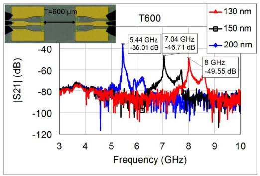

Fig. 2. Transmission parameter of SAW test structures with digit/interdigit of 130 nm, 150 nm and 200 nm
Two basic topologies are of choice for the IEF: (1) PI type configuration (Fig. 3 (a)) and (2) T-type configuration (Fig. 3 (b)). The general theory for the IEF design requires the fulfillment
of the following conditions for the SAW resonators (Fig. 4):
- fs,SAW_H=fo
- fp,SAW_H= fc2>fo
- fp,SAW_V=fo
- fs,SAW_V= fc1<fo (1)
where fo is the filter central operating frequency, fs is the series resonance frequency and fp is the parallel resonance frequency of the SAW-R, fc1 is the lower maximum rejection frequency and fc2 is the higher maximum rejection frequency.
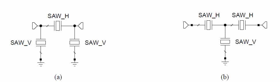

Fig. 3 BPF topologies for the final filter design: (a) PI-type configuration; (b) T-type configuration
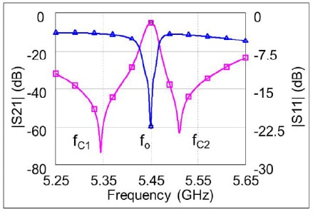

Fig. 4. Band pass filter characteristic and the definition of the central frequency and the rejection frequencies
This approach requires a strict control of the series and parallel resonance frequencies of the SAW-Rs. The effective processed on GaN/Si is limited to a maximum value of 0.3%, which leads to a difference between the two resonance frequencies of few MHz.
… read more at the full paper …
VIII. CONCLUSION
A new approach, which uses printed inductors connected in series or in parallel with the SAW-R for the accurate control of the series and parallel resonance frequencies was presented. At frequencies higher than 5 GHz, these inductors are in the 0.2-2 nH range and can be integrated monolithically into the SAW-R based filter structure, resulting in a very compact device. Printed inductors with values between 0.2-1 nH were placed in series with SAW-Rs with IDT digit/interdigit widths within the 130-200 nm range, operating in the 5.4 – 8.6 GHz frequency range. Test structures were designed and processed on a semi-insulating 1 µm thin epitaxial GaN layer, using advanced nanolithographic techniques. It was shown that the printed inductors tuned the series resonance frequencies with up to 0.75% leading to the development of a PI-configuration band-pass filter based on the impedance element approach. A moderate temperature coefficient (about -40 ppm/K) was measured for the test structures with printed inductors.
The dispersion of the resonance frequency across a quarter of a 3” wafer was investigated and compared to the influence of the main technological parameters (GaN layer thickness, metallization thickness, electrode width, variation of the elastic constants due to the thermal strain). The results indicate a main contribution of the variation of the thermal strain, together with the compensation techniques for minimum bowing of the wafer, to the frequency deviation (98 MHz).
A SAW-BPF design based on monolithic integration of printed inductors with SAW-Rs was proposed and circuit level simulation results were shown (insertion losses of 10.4 dB at 5.5 GHz, rejection better than 40 dB and 3 dB bandwidth of 8 MHz). It was shown that the insertion losses are mainly influenced by the mechanical losses and only slightly by the dielectric and conductive losses. The out of band rejection is mainly affected by the increase of the conductive and dielectric losses.
The main experimental results are presented during the conference – see the presentation link below.
ACKNOWLEDGEMENTS
This work was supported by the European Space Agency (Contract No. 40000115202/ 15/NL/CBi).
REFERENCES
[1]. K.Hashimoto, Surface Acoustic Wave Devices in Telecommunications, Springer-Verlag 2000 [2].
I.Wolf, Coplanar microwave integrated circuits, 1st ed., Verlagsbuchhandlung, 2006
[3]. A. Müller et al, “Nanoprocessing and Micromachining Technologies of GaN/Si for Sensors and
Filters Operating at Frequencies above 5 GHz”, ESA SPCD 2016
[4]. A.C. Bunea, A.M. Dinescu, L.A. Farhat, C. Pârvulescu, D. Neculoiu, “Effect of Key
Technological Parameters on GaN/Si SAW Resonators Operating Above 5 GHz”, Romanian Journal of
Information Science and Technology, vol. 20, No. 4, 2017, pp. 354-368
[5]. A. C. Bunea, D. Neculoiu and A. Dinescu, “GaN/Si monolithic SAW lumped element
resonator for C- and X- band applications”, 2017 IEEE Asia Pacific Microwave Conference
(APMC), Kuala Lumpar, 2017, pp. 1010- 1013.
[6]. K.-Y. Hashimoto, M. Kadota, T. Nakao, M. Ueda, M. Miura, H. Nakamura, H. Nakanishi,
K. Suzuki, “Recent development of temperature compensated SAW Devices,” in Proc. IEEE Int.
Ultrason. Symp., Oct. 2011, pp. 79– 86.
[7]. A. C. Bunea, A. M. Dinescu, C. Pârvulescu and D. Neculoiu, “Investigation of technological
dispersion of GaN on esonators for bandpass filter applications”, 2017 International
Semiconductor Conference (CAS),
inaia, 2017, pp. 123-126
read the full technical paper in pdf here:
![]()

and presentation here:
![]()

