
This blog article written by Youssef Laamimat, KYOCERA-AVX Components Corporation, discusses how to predict metal film capacitor lifetime by thermal simulation.
Introduction
In high-power applications like electric vehicles (EVs), customized metal film capacitors are often required to meet energy demands in a specific form factor.
These capacitors exhibit a strong temperature dependence of their bulk capacitance over time, which directly limits their total service life.
To maximize lifetime while minimizing space requirements, it is important to include accurate thermal simulation as part of the design process to ensure optimized and evenly distributed heat generation.
Metal Film Capacitors Construction
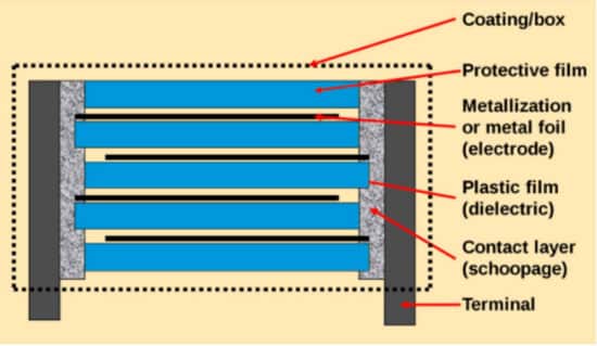
With the discovery of advanced polymers in the mid-20th century, a new capacitor was introduced that used plastic dielectrics to replace traditional paper-based designs. Figure 1 shows that a multi-layer sandwich of metal electrodes and plastic film separators creates a capacitive structure.
The electrodes are either deposited directly on the film (metallization) or are built from separate metal foils. The layered capacitor is wound on a bobbin, and a terminal contact layer is deposited to connect everything in parallel. These devices are commonly known as metal film capacitors.
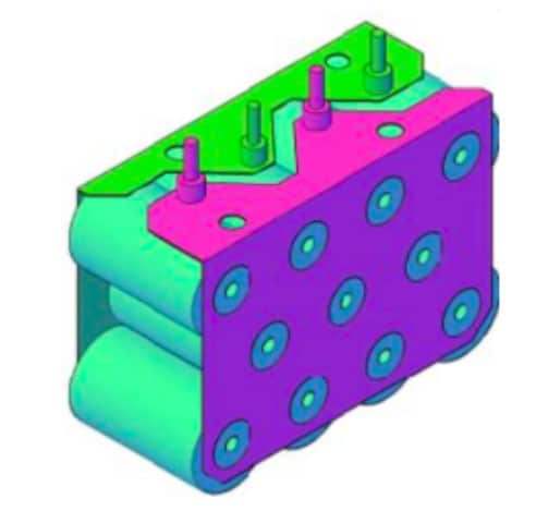
Individual bobbins can be customized for shape, size, and capacitance and connected in banks to form the final device. An example is shown in Figure 2, where eleven bobbins are connected in parallel and interfaced via two sets of terminals.
The arrangement of the bobbins can be optimized to suit the available space, resulting in excellent volumetric efficiency. The arrays can also be balanced for current and inductance to eliminate expansion problems, enabling operation across a temperature range of -55 °C to +125° C. These qualities make metal-film capacitors ideal for electric vehicles (EV) applications where high reliability and harsh environmental tolerance is critical.
Life Expectancy of Film Capacitors
Unlike electrolytic capacitors that create a catastrophic short circuit after failure, metal-film capacitors exhibit a unique self-healing property. Whenever the dielectric fails, the resulting local heat vaporizes the metallization and opens the short circuit. As such, film capacitors experience a parametric loss of capacitance of about 5% over their lifetime with no catastrophic failure mode.
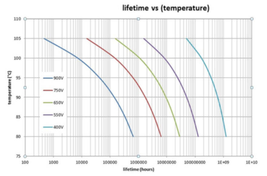
This graceful failure characteristic is another reason film capacitors are a great fit for EV applications. The lifetime of film capacitors is very dependent on environmental and electrical factors. Unlike other devices, vibration, shock, and humidity have minimal effect. However, electrical factors play a leading role in determining reliability, including operating voltage, ripple current, and charge-discharge duty cycle. In addition, ambient temperature and internal heating due to ripple current are very critical. This is demonstrated in Figure 3, where the operational lifetime is shown as a function of both temperature and applied voltage for a common metal film capacitor.
The lifetime, in this case, is quantified by a specified decrease in bulk capacitance and ranges six orders of magnitude. It is worth noting that even after the end of life point, the capacitors will continue to function without catastrophic failure, giving the designer several degrees of freedom to maximize reliability.
Thermal Modeling of Metal Film Capacitors
Since temperature is such a strong lever in film capacitor lifetime, KYOCERA AVX uses a multiphysics simulator to properly characterize custom capacitors’ thermal performance to maximize their life expectancy. This is particularly relevant in EV applications where proximity to other heatgenerating electronics and overall self-heating due to voltage ripple demand the designer’s attention.
The capacitor consists of physical elements such as housing, resin, bobbins (metalized film), busbars, and insulators. Each element is defined by its specific thermal properties, including electrical and thermal conductivity. As the main element of the capacitor, the bobbin is the most complex to model. It is typically constructed with anisotropic materials that depend on the direction of metallization and the thickness of the film. The generated heat from the bobbins is induced by the RMS current, the number of bobbins, and their resistance characteristics.
The busbar is the second major component of the capacitor. Traditional coupled Joule heating is used with specific properties of the material (CuA1) and the DC current going through the part (by the selected DC surfaces) to simulate the heat from the busbars.
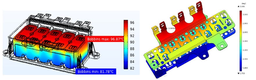
Common input parameters to the simulation may include ambient temperature, nearby power devices, connector characteristics, and AC/DC current. The result of such a simulation is shown in Figure 4, where the range of bobbin temperatures is shown throughout the device and the busbar contributions are included.
These results allow designers to alter the bobbin shape, size, orientation, and connection methods to minimize hot spots and peak temperature distribution. This, in turn, will extend the lifetime of the part and enable greater design freedom in other areas that may be constrained.
Case Study
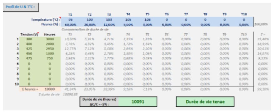
Following the different voltages and duration distributions given by an example customer, different hotspot temperatures (T1, …T5) can be calculated. The end of life of the capacitor can be simulated as a maximum -5% drift of the initial bulk capacitance. Figure 5 shows that the initial lifetime calculated for this custom capacitor is approximately 10,000 hours.
In this example, the primary hotspot is located under the IGBT connections to the capacitor.
The temperature at this point directly heats the bobbins without any thermal path for dissipation. A thermal sink was added to dissipate this heat before reaching the bobbins by making a minor internal design change. A reduction of several degrees of temperature was simulated and confirmed with thermocouples on the physical device. This modification made the customer’s 50,000-hour lifetime goal achievable.
Conclusions
While metal film capacitors are ideal in many high-power applications, including automotive EVs, a thorough understanding of their thermal characteristics is critical to achieving design success. Since these capacitors are often customized specifically for their end-use, advanced electrical and thermal simulation tools can be used to accurately predict film capacitors’ operating corners.
The results of these simulations can inform very basic design changes that have profound effects on the lifetime and reliability of the capacitors.

