

Passive Components Blog
No Result
View All Result
  • Home
  • News
    • All
    • Aerospace & Defence
    • Antenna
    • Applications
    • Automotive
    • Capacitors
    • Circuit Protection Devices
    • electro-mechanical news
    • Filters
    • Fuses
    • Inductors
    • Industrial
    • Integrated Passives
    • inter-connect news
    • Market & Supply Chain
    • Market Insights
    • Medical
    • Modelling and Simulation
    • New Materials & Supply
    • New Technologies
    • Non-linear Passives
    • Oscillators
    • Passive Sensors News
    • Resistors
    • RF & Microwave
    • Telecommunication
    • Weekly Digest
    onsemi solid-state transformer concept for 800 V HVDC AI data center power conversion with SiC modules, DC-link capacitors and high-frequency magnetics

    Solid-State Transformers for 800 V AI Data Centers: Passive Component Design Considerations

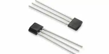
    Littelfuse TX00AT314AMA omnipolar TMR magnetic switch sensor in a leaded TO-92-3 through-hole package

    Littelfuse Expands Omnipolar TMR Switch with Leaded TO-92 Package Option

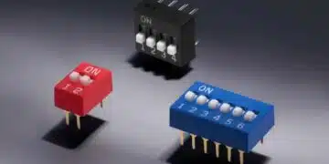
    SCHURTER THT DIP Switches Support Hardware-Level Configuration

    TDK CN series 10 µF 100 V X7R soft-termination multilayer ceramic capacitor in 3225 EIA 1210 package

    TDK Releases 100 V Soft-Termination X7R MLCCs 10 uF in 3225 Package

    Compact inductive rotary position encoder sensor near a motor shaft, representing the Vishay RAIK045I MP encoder category

    Vishay Introduces 16-Bit Inductive Encoder for Motor-Adjacent Position Sensing

    Hirose FH51 automotive FPC/FFC connector with low-profile receptacle construction and top-and-bottom contact arrangement

    Hirose Automotive FPC/FFC Connector Adds One-Action Mating up to 125°C

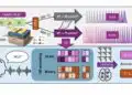
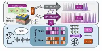
    Overview of fabricated ferroelectric capacitors improving hyperdimensional computing task learning accuracy. a The experimental work reported in this study comprises ferroelectric capacitor (FeCAP) device fabrication, structural and electrical characterization, analog state identification and their reliability study. b The computational part of the work explores the benefits of using characteristics from the fabricated devices in a hyperdimensional computing scheme; source: authors

    High-Precision Hyperdimensional Computing with Multi-Level Ferroelectric HZO Capacitors

    Coilcraft Introduces Automotive Common Mode Chokes Target CISPR 25 Class 5 EMC Compliance

    Murata Expands Automotive Metal Power Inductor Range

    Trending Tags

    • Ripple Current
    • RF
    • Leakage Current
    • Tantalum vs Ceramic
    • Snubber
    • Low ESR
    • Feedthrough
    • Derating
    • Dielectric Constant
    • New Products
    • Market Reports
  • Knowledge Blog
  • Dossiers
    • AI Hardware Dossier
    • Automotive Dossier
    • Industrial Robotics Dossier
    • Power Converter Dossier
    • Capacitor Dossier
    • Resistor Dossier
    • Inductor Dossier
    • Circuit Protection Dossier
  • Suppliers
    • Who is Who
  • PCNS
    • PCNS 2025
    • PCNS 2023
    • PCNS 2021
    • PCNS 2019
    • PCNS 2017
  • Events
  • Home
  • News
    • All
    • Aerospace & Defence
    • Antenna
    • Applications
    • Automotive
    • Capacitors
    • Circuit Protection Devices
    • electro-mechanical news
    • Filters
    • Fuses
    • Inductors
    • Industrial
    • Integrated Passives
    • inter-connect news
    • Market & Supply Chain
    • Market Insights
    • Medical
    • Modelling and Simulation
    • New Materials & Supply
    • New Technologies
    • Non-linear Passives
    • Oscillators
    • Passive Sensors News
    • Resistors
    • RF & Microwave
    • Telecommunication
    • Weekly Digest
    onsemi solid-state transformer concept for 800 V HVDC AI data center power conversion with SiC modules, DC-link capacitors and high-frequency magnetics

    Solid-State Transformers for 800 V AI Data Centers: Passive Component Design Considerations

    Littelfuse TX00AT314AMA omnipolar TMR magnetic switch sensor in a leaded TO-92-3 through-hole package

    Littelfuse Expands Omnipolar TMR Switch with Leaded TO-92 Package Option

    SCHURTER THT DIP Switches Support Hardware-Level Configuration

    TDK CN series 10 µF 100 V X7R soft-termination multilayer ceramic capacitor in 3225 EIA 1210 package

    TDK Releases 100 V Soft-Termination X7R MLCCs 10 uF in 3225 Package

    Compact inductive rotary position encoder sensor near a motor shaft, representing the Vishay RAIK045I MP encoder category

    Vishay Introduces 16-Bit Inductive Encoder for Motor-Adjacent Position Sensing

    Hirose FH51 automotive FPC/FFC connector with low-profile receptacle construction and top-and-bottom contact arrangement

    Hirose Automotive FPC/FFC Connector Adds One-Action Mating up to 125°C

    Overview of fabricated ferroelectric capacitors improving hyperdimensional computing task learning accuracy. a The experimental work reported in this study comprises ferroelectric capacitor (FeCAP) device fabrication, structural and electrical characterization, analog state identification and their reliability study. b The computational part of the work explores the benefits of using characteristics from the fabricated devices in a hyperdimensional computing scheme; source: authors

    High-Precision Hyperdimensional Computing with Multi-Level Ferroelectric HZO Capacitors

    Coilcraft Introduces Automotive Common Mode Chokes Target CISPR 25 Class 5 EMC Compliance

    Murata Expands Automotive Metal Power Inductor Range

    Trending Tags

    • Ripple Current
    • RF
    • Leakage Current
    • Tantalum vs Ceramic
    • Snubber
    • Low ESR
    • Feedthrough
    • Derating
    • Dielectric Constant
    • New Products
    • Market Reports
  • Knowledge Blog
  • Dossiers
    • AI Hardware Dossier
    • Automotive Dossier
    • Industrial Robotics Dossier
    • Power Converter Dossier
    • Capacitor Dossier
    • Resistor Dossier
    • Inductor Dossier
    • Circuit Protection Dossier
  • Suppliers
    • Who is Who
  • PCNS
    • PCNS 2025
    • PCNS 2023
    • PCNS 2021
    • PCNS 2019
    • PCNS 2017
  • Events
No Result
View All Result
Passive Components Blog
No Result
View All Result

R, L, C, and a PCB Trace Impedance Measurement and Simulation

28.12.2018
Reading Time: 8 mins read
A A

Source: InCompliance Mag article

by Bogdan Adamczyk and Jim Teune in EMC Concepts Explained.

RelatedPosts

Solid-State Transformers for 800 V AI Data Centers: Passive Component Design Considerations

Littelfuse Expands Omnipolar TMR Switch with Leaded TO-92 Package Option

SCHURTER THT DIP Switches Support Hardware-Level Configuration

This article investigates the impedance of the three standard passive circuit components (R, L, and C) as well as the frequency response of a PCB trace. It is shown that a PCB trace can be modeled as a resonant RLC network just like the standard components and effectively constitutes the fourth circuit component whose frequency behavior directly effects the impedance of the resistors, inductors, and capacitors on a PCB.

1. Component Models and Simulations

Actual circuit components exhibit non ideal effects that can be modeled by augmenting the ideal model with a parasitic resistance, inductance and capacitance. The parasitics for the three standard components (R, L, and C) considered in this section come from the component itself and not from the connecting traces. The parasitics associated with a PCB trace considered in this section come from the trace itself and not from the other circuit components.

1.1 Resistor

Circuit model and the impedance vs. frequency curve (straight-line approximation) for a resistor and its parasitics (with no traces attached) are shown in Figure 1 [1].

Figure 1: Resistor circuit model and its impedance curve

The parasitic inductance and capacitance in Figure 1 are inherent to the component itself and the fabrication method, and are not attributed to the connecting traces. Figure 2 shows the simulation results for a 300-Ω surface mount resistor together with its realistic parasistics (simulation is run between 1 MHz and 1 GHz).

Figure 2: Resistor with its parasitics – impedance vs. frequency (no connecting traces)

The low-frequency impedance stays at 49.5 dB and drops by 1 dB at 1 GHz. The self resonant frequency is well above 1 GHz and thus not shown in the simulation. This simulation result will be confirmed in the measurement section.

1.2 Inductor

Circuit model and the impedance vs. frequency curve for an inductor with its parasitics (with no traces attached) are shown in Figure 3.

Figure 3: Inductor circuit model and impedance curve impedance vs. frequency (no connecting traces)


Figure 4
shows the simulation results for a 220-nH inductor together with its realistic parasistics.

Figure 4: Inductor with its parasitics – impedance vs. frequency (no connecting traces)


The self-resonant frequency of the inductor is 638.2 MHz – this result will be confirmed in the measurement section.

1.3 Capacitor

Circuit model and the impedance vs. frequency curve for a capacitor with its parasitics (with no traces attached) are shown in Figure 5 [2].

Figure 5: Capacitor circuit model and impedance curve


Figure 6
 shows the simulation results for a 120-pF capacitor together with its realistic parasistics.

Figure 6: Capacitor with its parasitics –impedance vs. frequency (no connecting traces)


The self-resonant frequency of the capacitor is 995.2 MHz – this result will be confirmed in the measurement section.

1.4 PCB Trace

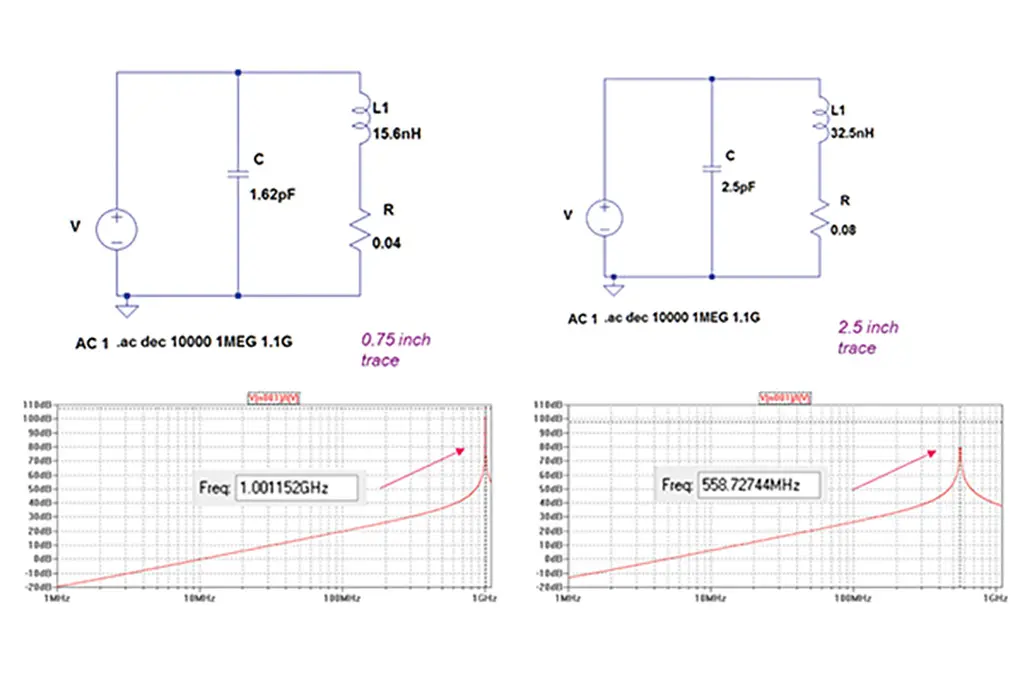
Figure 7 shows the circuit models and the impedance curves for two PCB traces of length 0.75 and 2.5 inches, respectively.

Figure 7: PCB traces with their parasitics – circuit model and impedance vs. frequency (no components attached)


Comparison of these curves with the one in Figure 4 reveals that an unpopulated PCB trace acts as an inductor! The longer trace has larger inductance and hence its self resonant frequency is lower than that of the shorter trace.

These are two very important observations since in any practical circuit, the standard three passive components (R, L, and C) will be connected to other components with PCB traces. These traces will act as the fourth circuit component whose impact will depend on its trace length. The measurement section will illustrate this impact.


2. Impedance Measurements

The experimental boards used for impedance measurements are shown in Figure 8 [3].

Figure 8: PCB boards used for impedance measurements


The measurement setup is shown in
Figure 9.

Figure 9: Measurement setup


2.1 PCB Trace

Figure 10 shows the impedance measurement of two unpopulated PCB traces of length 0.75, and 2.5 inches, respectively.

Figure 10: PCB Trace – impedance measurements: a) short trace, b) long trace


Note that the results in Figure 10 are consistent with the simulation results in Figure 7. The short trace resonates at 1 GHZ while the long one resonates at a frequency of 559.8 MHz. This behavior is the direct consequence of the increase in the trace inductance.

2.2 Resistor

Figure 11 shows the impedance measurement of a 300-Ω resistor with no connecting traces and with the PCB traces of length 0.75, and 2.5 inches, respectively. (Resistor used is Stackpole Electronics, Inc. RMCF0805JT300R).

Figure 11: Resistor – impedance measurements with: a) no trace, b) short trace, c) long trace


Note that the result in Figure 11a is consistent with the simulation result in Figure 2. When the resistor is attached with a short PCB trace, the 3-dB point moves from the GHz range to the frequency of 835 MHz. As the trace length increases, this point moves to the left (522 MHz), which is the direct consequence of the increase in the trace inductance.

2.3 Inductor

Figure 12 shows the impedance measurement of a 220-nH inductor with no connecting traces and with the PCB traces of length 0.75, and 2.5 inches, respectively. (Inductor used is Murata, LQG18HHR22J00).

Figure 12: Inductor – impedance measurements with: a) no trace, b) short trace, c) long trace


Note that the result in Figure 12a is consistent with the simulation result in Figure 4. When the inductor is attached with a short PCB trace, the self resonant frequency point moves from 638.2 MHz to 559.5 MHz. As the trace length increases, this frequency shifts to the left, to 278.6 MHz, which is the direct consequence of the increase in the trace inductance.

What is noteworthy here is the fact that the inductor connected with a short trace resonates at the same frequency as the unpopulated long PCB trace itself! This result supports the simulation conclusion in Section 1.4: an unpopulated PCB trace acts as an inductor!

2.4 Capacitor

Figure 13 shows the impedance measurement of a 120-pF capacitor with no connecting traces and with the PCB traces of length 0.75, and 2.5 inches, respectively. (Capacitor used is Murata, CGM1885C1H121JA16).

Figure 13: Capacitor – impedance measurements with: a) no trace, b) short trace, c) long trace


Note that the result in Figure 13a is consistent with the simulation result in Figure 6. When the capacitor is attached with a short PCB trace, the self resonant frequency point moves from 993.2 MHz to 612.4 MHz. As the trace length increases, this frequency shifts to the left, to 117.5 MHz, which is the direct consequence of the increase in the trace inductance. Additionally, an anti-resonance point is present at 901.5 MHz frequency.


References

  1. Bogdan Adamczyk, Foundations of Electromagnetic Compatibility with Practical Applications, Wiley, 2017.
  2. Adamczyk, B., Teune, J., “Impact of a Trace Length on Capacitor Frequency Response,” In Compliance Magazine, March 2018.
  3. Bill Spence and Pete Vander Wel, “Designers of the PCB used for impedance measurements,” Gentex Corp, 2008.


Dr. Bogdan Adamczyk
is a professor and the director of the EMC Center at Grand Valley State University
(http://www.gvsu.edu/emccenter) where he performs research and develops EMC educational material. He is an iNARTE certified EMC Master Design Engineer, a founding member and the chair of the IEEE EMC West Michigan Chapter. Prof. Adamczyk is the author of the textbook “Foundations of Electromagnetic Compatibility with Practical Applications” (Wiley, 2017). He can be reached at [email protected].

Jim Teune is a founding partner of E3 Compliance LLC which specializes in product development and EMC precompliance testing. He is an iNARTE certified EMC Engineer and Master EMC Design Engineer. Jim is an industrial partner of the EMC Center at GVSU. He can be reached at [email protected].

 

Related

Recent Posts

onsemi solid-state transformer concept for 800 V HVDC AI data center power conversion with SiC modules, DC-link capacitors and high-frequency magnetics

Solid-State Transformers for 800 V AI Data Centers: Passive Component Design Considerations

9.9.2026
23
TDK CN series 10 µF 100 V X7R soft-termination multilayer ceramic capacitor in 3225 EIA 1210 package

TDK Releases 100 V Soft-Termination X7R MLCCs 10 uF in 3225 Package

9.9.2026
5
Compact inductive rotary position encoder sensor near a motor shaft, representing the Vishay RAIK045I MP encoder category

Vishay Introduces 16-Bit Inductive Encoder for Motor-Adjacent Position Sensing

9.9.2026
4
Overview of fabricated ferroelectric capacitors improving hyperdimensional computing task learning accuracy. a The experimental work reported in this study comprises ferroelectric capacitor (FeCAP) device fabrication, structural and electrical characterization, analog state identification and their reliability study. b The computational part of the work explores the benefits of using characteristics from the fabricated devices in a hyperdimensional computing scheme; source: authors

High-Precision Hyperdimensional Computing with Multi-Level Ferroelectric HZO Capacitors

7.9.2026
19

Coilcraft Introduces Automotive Common Mode Chokes Target CISPR 25 Class 5 EMC Compliance

7.9.2026
15

Murata Expands Automotive Metal Power Inductor Range

7.9.2026
33

Bourns Releases Low-Profile Incremental Ring Encoder Targets Compact Industrial HMIs

7.9.2026
3

August 2026 Interconnect, Passives and Electromechanical Components Market Insights

4.9.2026
35

Knowles Cornell Dubilier 105C Flatpack Aluminum Electrolytic Capacitors Target Low-Profile High-Density Power Designs

4.9.2026
33

Upcoming Events

Sep 10
11:00 - 12:00 CEST

Equipment models and model strategies for Space Missions

Sep 16
17:00 - 18:00 CEST

Designing a 5 kW, 800 V-to-50 V PSFB Converter for Next-Generation Data Centers

Sep 29
16:00 - 17:00 CEST

Cybersecurity 2026

View Calendar

Popular Posts

  • Buck Converter Design and Calculation

    0 shares
    Share 0 Tweet 0
  • LLC Resonant Converter Design and Calculation

    0 shares
    Share 0 Tweet 0
  • Boost Converter Design and Calculation

    0 shares
    Share 0 Tweet 0
  • Flyback Converter Design and Calculation

    0 shares
    Share 0 Tweet 0
  • Earthing Systems and IEC Classification Explained

    0 shares
    Share 0 Tweet 0
  • MLCC and Ceramic Capacitors

    0 shares
    Share 0 Tweet 0
  • Resistor Symbols

    0 shares
    Share 0 Tweet 0
  • Capacitor Charging and Discharging

    0 shares
    Share 0 Tweet 0
  • Audio Capacitors: Choosing Capacitors for Crossover Circuits

    0 shares
    Share 0 Tweet 0
  • Thermistors Basics, NTC and PTC Thermistors

    0 shares
    Share 0 Tweet 0

Newsletter Subscription


Passive Components Blog

© 2015–2026
All rights reserved

  • Home
  • Privacy Policy
  • EPCI Membership & Advertisement
  • About

No Result
View All Result
  • Home
  • Knowledge Blog
  • Dossiers
  • PCNS

© 2015–2026
All rights reserved