The ratification of the ANSI/VITA 90 (VNX+) family of standards marks an important step for compact, rugged embedded systems that must combine high compute density with demanding RF, optical and high‑speed digital I/O.
The choice of Samtec interconnects at the heart of VNX+ gives system designers a standardized path to improve signal integrity while reducing size, weight and power in harsh environments.
Why VNX+ matters for embedded designers
VNX+ builds on the original VNX concept while staying mechanically compatible, but significantly upgrades the interconnect and system capabilities for next‑generation small form factor designs in industrial, military and aerospace markets. It does this by combining high‑speed digital connectors, high‑frequency RF, and pluggable optics within a compact, conduction‑cooled module footprint according to the ANSI/VITA 90 framework.
The standard aims squarely at applications where board space is limited, environmental conditions are harsh and long‑term reliability is critical, such as mission systems, avionics, edge computing nodes and compact sensor/processing payloads.
Key features and benefits
From an interconnect and module‑level perspective, the VNX+ VITA 90 family brings several engineering‑relevant advantages:
- Mechanical backward compatibility with the original VNX framework, easing migration of existing designs and reuse of mechanical chassis concepts.
- Enhanced mechanical robustness and conduction‑cooled operation, improving resistance to shock, vibration and temperature extremes typical in defense and aerospace platforms.
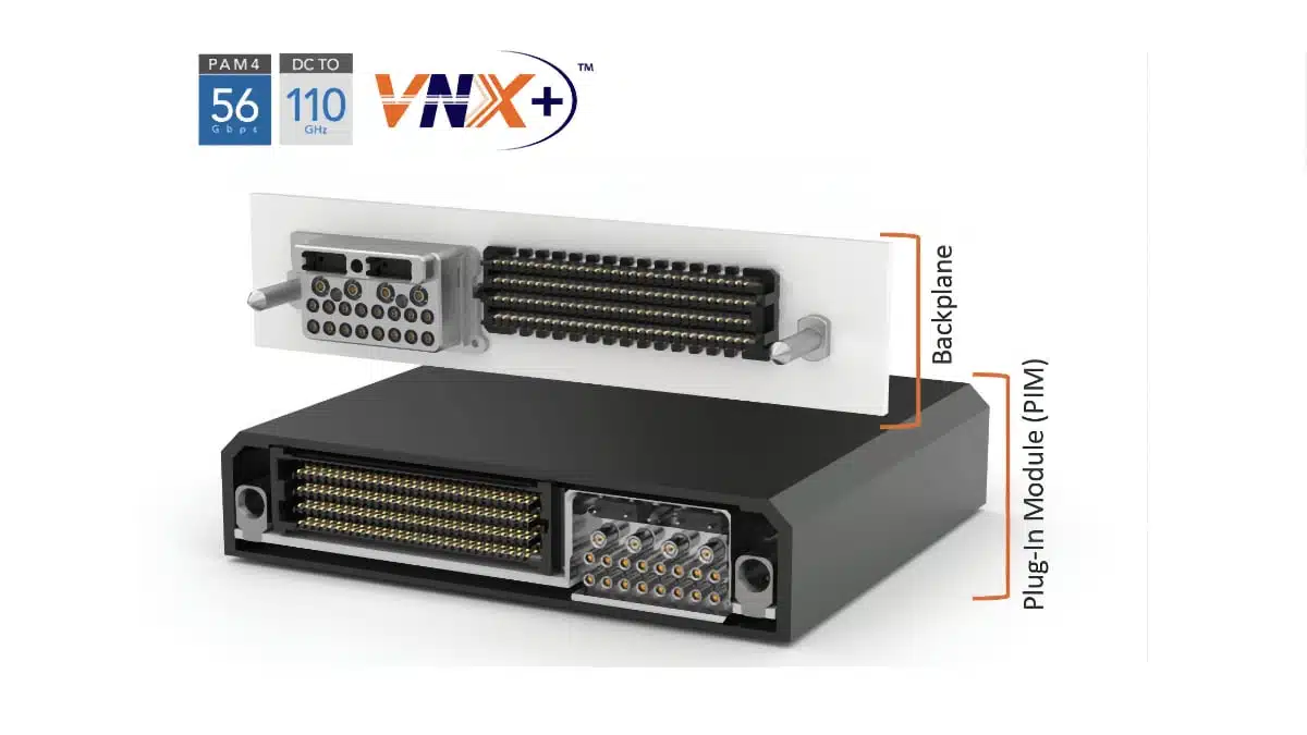
- Integrated high‑speed signaling enabled by Samtec SEARAY arrays supporting data rates up to 56 Gbps PAM4 per differential pair, suitable for PCIe, Ethernet and other modern serial interfaces.
- High‑density RF backplane connectivity with support up to 110 GHz, allowing true microwave/mmWave functions (radar, EW, high‑frequency links) within the same module ecosystem.
- Support for pluggable optics via Samtec FireFly or FireHawk optical assemblies with MT ferrule terminations, enabling very high aggregate bandwidth with reduced copper cabling complexity.
- Blind‑mate guidance and rugged connector mechanics, reducing the risk of damage during insertion/removal and supporting field‑replaceable modules.
For system architects, this combination of features translates into higher functional density per slot, improved signal integrity for high‑data‑rate links and a simplified approach to mixing RF, optical and digital interfaces in a repeatable, standards‑based form factor.
VNX+ ecosystem and “dot standards”
The VNX+ family is defined as a set of related “dot standards” under ANSI/VITA 90, each describing specific interface profiles and configuration options. In practice, this means:
- Multiple profiles to cover different mixes of high‑speed digital, RF and optical I/O.
- Scalable module definitions that can be reused across different programs and platforms.
- Interoperability between vendors who follow the same profiles, reducing lock‑in and easing second‑source strategies.
For purchasing teams and program managers, the dot‑standard approach is important because it enables long‑term ecosystem growth and mitigates lifecycle risk compared with proprietary small form factor solutions.
Typical applications
VNX+ targets rugged small form factor embedded computing where SWaP constraints are severe but bandwidth and reliability requirements are high. Typical use cases include:
- Aerospace and defense mission computers, where multiple high‑speed sensor streams and control interfaces must be aggregated in a compact flight‑qualified module.
- Radar, electronic warfare and SIGINT front‑ends, leveraging the 110 GHz RF capability for high‑frequency signal chains combined with digital processing.
- Rugged edge computing and gateway nodes in industrial automation, transportation and energy, where conduction cooling and vibration resistance are key.
- High‑density data acquisition, sensor fusion and imaging systems that need a mix of high‑speed serial links, RF and optical connectivity in a constrained volume.
- Space‑constrained test and measurement or portable systems that reuse VNX+ modules as configurable I/O and processing building blocks.
In many of these cases, the combination of conduction cooling and blind‑mate backplane connectivity helps designers achieve reliable operation over extended temperature ranges and under mechanical stress.
Technical highlights of VNX+ interconnects
VNX+ is built around a specific set of Samtec interconnect technologies selected to meet the mechanical and electrical goals of the standard:
- High‑density RF backplane systems
These support operation up to 110 GHz, allowing true microwave/mmWave interfaces on the backplane. For designers, this means RF paths can be kept short and well‑controlled inside the chassis instead of relying on long coax harnesses. - SEARAY high‑speed arrays
SEARAY arrays in VNX+ support signaling up to 56 Gbps PAM4 per lane. This level of performance is appropriate for modern high‑speed serial protocols such as PCI Express, 100G/200G/400G Ethernet variants and custom SerDes, depending on system architecture and PHY selection. - Rugged blind‑mate guidance
The blind‑mate design and guidance hardware help ensure reliable mating in the field, especially where access is limited or the module must be inserted into a deep chassis slot. This is relevant not only for reliability but also for maintenance turnaround times. - Pluggable optics with FireFly and FireHawk
The VNX+ standard provides optics slots that can be populated with Samtec FireFly or FireHawk optical modules using MT ferrules on the far end. This gives designers a modular way to add very high bandwidth, long‑reach links without changing the core mechanics of the module. - QMC mezzanine card interconnect
Samtec’s QMC mezzanine interconnect fits inside the VNX+ module envelope and allows stacking of expansion cards. This can be used to add I/O ports, accelerators or application‑specific functions for both front and rear I/O configurations.
Exact connector part numbers, pinouts and mechanical details should be taken from the official Samtec and ANSI/VITA 90 documentation and datasheets.
Design‑in notes for engineers
When considering VNX+ for a new or updated design, engineers should keep several practical points in mind:
- System architecture
Decide early how much high‑speed digital, RF and optical I/O the application needs and choose the appropriate VNX+ profile. This will affect connector selection, backplane routing strategy and thermal design. - Signal integrity
At 56 Gbps PAM4 and up to 110 GHz RF, PCB layout, backplane materials and stack‑ups are critical. Work from Samtec’s recommended design rules, launch geometries and material guidance, and budget for detailed channel simulation. - Thermal and mechanical design
Conduction cooling requires careful mechanical design of the module, wedgelocks or other clamping systems, and the chassis sidewalls or cold plates. Verify that expected power dissipation per module can be handled over the full operating temperature range. - Modularity and expansion
Consider whether QMC mezzanine expansion will be needed in the lifecycle of the platform. Designing in QMC early may simplify future upgrades or program variants that need extra I/O or processing capability. - Supply chain and lifecycle
Because VNX+ is a standards‑based ecosystem, multiple programs can share common interconnect and backplane building blocks. This can simplify qualification, reduce inventory complexity and support long‑term availability strategies.
For teams transitioning from legacy VNX or other small form factor standards, leveraging the mechanical compatibility of VNX+ can reduce non‑recurring engineering effort on enclosures and mechanics while modernizing the electrical and I/O capabilities.
Source
This article is based on information provided in an official Samtec blog press release announcing the ratification of the ANSI/VITA 90 (VNX+) family of standards and the selection of Samtec interconnects for the VNX+ ecosystem, complemented by general engineering context.