SMD surface mount inductors can be easily mounted by fast pick and place machines and thus reduce its placement cost. The technology also supports high level of miniaturization and downsizing of electronics.
SMD Multilayer inductors
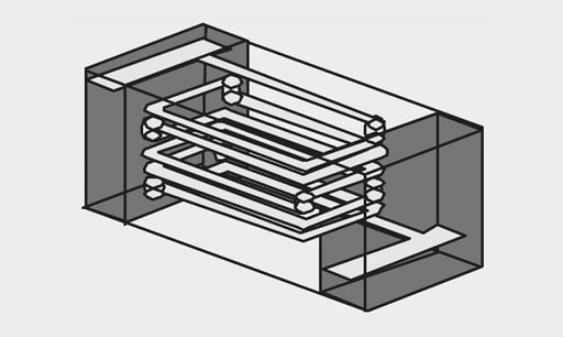
If the wire windings on the outside of a conventional “coil” are mounted inside the coil body, the so-called multilayer SMD inductor (Figure 1. and 2.) is created.

The ferrite body magnetically shields the component, significantly reducing external interference and cross-talk. The multilayer inductor may be seen as a “compromise” between the ceramic inductor and SMD ferrite. This component is especially suitable as an inductor in filters and resonant circuits where low interference from external signals is required and in circuits with high packing density.
Practical tips:
- Do not operate in the self-resonant range
- Observe max. current loading capacity
- Low DC resistance, therefore also suitable for low-voltage systems
Power Multilayer Inductors
The miniaturization of SMD components, especially inductors, is a widespread trend in portable devices, as it is especially storage chokes that frequently require the most space. Wired components are out of the question in these orders of magnitude. This is where the power multilayer types (Figure 3.) apply.
In order to allow minimization of the coil volume, the switching controller IC is driven at ever-higher switching frequencies. Switching controllers like the Micrel MIC2285 already work with 4 MHz. The dimensions of the storage chokes required can therefore be reduced by up to 90%. The compact power multilayer inductors in 1008 package (2.5 mm x 2.0 mm x 1.0 mm) not only offer high rated currents (up to 2.4 A), but also a lower DCR than comparable to standard multilayer inductors types.
The saturation current of the power multilayer inductors (such as WE-PMIs) relates to the typical inductance drop of –30% from the zero current inductance. The rated current is defined for the common self-heating of DT = 40 K with respect to the ambient temperature.
The used NiZn core material allows the use of the power inductors WE-PMI series up to 10 MHz. The multilayer types are especially suitable for power supplies in portable devices.
SMD – Wire Wound Inductor /SMD RF Inductor
Wound inductors are available also in SMD packages (Figure 6.). Individual types may essentially differ in their mechanical construction. Whereas components as WE-GF in Figure 6. right is completely embedded in plastic and can therefore handle high humidity very effectively, the other types (WE-LQ – Figure 6. left) is in an open package. It can therefore be loaded with higher currents at the same inductance in relation to its package volume.
In Figure 7. and 8. the layout of the SMD RF Inductor is shown graphically. A wire-wrapping surrounds a ferrite body. The special ferrite mixture faciliates a wide inductance spectrum despite the miniature ferrite core.