
Sulphur contamination has become a silent reliability killer for film chip resistors in industrial electronics, IT infrastructure and outdoor equipment. This post explains the physics of sulphur‑induced failures, compares standard and sulphur‑resistant resistor constructions, and gives practical guidance for part selection and design‑in.
Key Takeaways
- Sulphur contamination threatens the reliability of film chip resistors, especially in industrial and outdoor applications.
- Standard resistors fail due to silver sulphide formation when exposed to sulphur-rich environments.
- Sulphur-resistant resistors use a protective layer to prevent sulphur ingress, significantly reducing failure risks.
- Designers should choose sulphur-resistant resistors in environments with high sulphur exposure or for critical applications.
- These resistors offer increased reliability, improving uptime and reducing maintenance costs in data-critical systems.
Why Sulphur Environments Matter
Film chip resistors with silver (Ag) or silver‑palladium (AgPd) terminations are widely used thanks to their cost and manufacturability. In sulphur‑rich atmospheres, these terminations can react to form non‑conductive silver sulphide, eventually driving resistors open circuit.
Typical sulphur sources and conditions include:
- Use of oils, lubricants and fossil fuels.
- Presence of rubber seals, gaskets, grommets and molded coatings.
- Air‑polluted industrial areas or locations with biological or volcanic gases.
Applications at particular risk are:
- IT: servers, storage systems, notebooks and desktop computers.
- Telecom: communication base stations.
- Industrial: motor and pump controls, welding equipment.
- Process industries: rubber, paper and oil manufacturing.
- Outdoor: road lighting, traffic control, marine, mining, agricultural and winery equipment.
In these systems, a single open resistor in a bias or sense path can disable an interface, power rail or protection function, leading to disproportionate system‑level impact.
Failure Mechanism in Standard Film Resistors
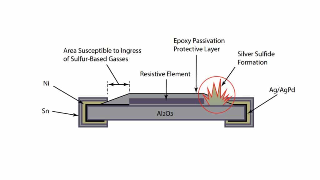
A standard film chip resistor consists of a ceramic substrate, Ag/AgPd internal terminations, a screen‑printed resistive film, epoxy passivation and an external Ni/Sn terminal finish. The epoxy layer does not completely cover the internal Ag/AgPd termination, leaving a vulnerable path for sulphur ingress.
In a sulphur environment:
- Sulphur‑bearing gases diffuse through the passivation and along interfaces.
- Silver in the Ag/AgPd termination reacts to form silver sulphide.
- Silver sulphide growth can crack the ceramic or progressively increase resistance until the part goes open circuit.
Once silver sulphide has formed along the length of the terminal, the conductive cross‑section is reduced, causing a resistance increase that can be difficult to detect in‑circuit until hard failure occurs.
Standard vs. Sulphur‑Resistant Construction
Sulphur‑resistant film resistors introduce an additional protective structure around the Ag‑based termination. Certain manufacturers, for example, uses a palladium (Pd) protection layer that fully covers the Ag terminals, blocking the sulphur diffusion path.
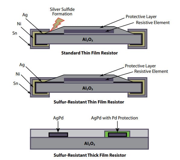
Table 1 – Structural comparison
| Feature | Standard film resistor | Sulphur‑resistant film resistor |
|---|---|---|
| Internal termination material | Ag or AgPd, partly covered by epoxy passivation | Ag or AgPd fully covered by Pd (or similar) barrier layer |
| Passivation coverage | Epoxy partially covers Ag/AgPd, exposed edge exists | Epoxy plus metallic barrier over Ag/AgPd area |
| Terminal outer finish | Ni barrier + matte Sn solder layer | Ni barrier + matte Sn, same application method |
| Sulphur ingress path | Through epoxy and along exposed Ag/AgPd interface | Blocked at Pd (or barrier) layer, minimal ingress |
| Typical failure mode in sulphur | Open circuit via silver sulphide and cracking | Strongly reduced probability of sulphide‑induced opens |
From an assembly and electrical point of view, sulphur‑resistant resistors are used identically to standard film resistors; the change is entirely in termination design and materials.
Example: Impact on a Data Center
In a server farm located in an industrial area with sulphur contamination, standard film resistors in memory modules or interface boards can suffer from progressive sulphide‑induced opens. Replacing these with sulphur‑resistant versions can virtually eliminate this specific failure mode, improving uptime and reducing unplanned maintenance.
When to Specify Sulphur‑Resistant Resistors
While the original article focuses on IT and telecom, the same decision logic applies across many sectors. Below is a practical checklist you can adapt for design guidelines.
Environmental and application triggers
Specify sulphur‑resistant film resistors when one or more of the following are present:
- Location in or near refineries, paper mills, rubber manufacturing, or heavy traffic corridors.
- Equipment installed in plants using large quantities of oils, lubricants or fossil fuels.
- Use of elastomeric seals, gaskets and molded rubber parts near the PCB.
- Outdoor or semi‑outdoor deployment (lighting, traffic control, marine, agricultural machinery).
- Data‑critical systems where downtime cost is high (server farms, banking, telecom cores).
Circuit‑level criticality
Upgrade to sulphur‑resistant parts for resistors that:
- Provide biasing or feedback in power supplies and regulators.
- Implement sensing functions (current sense, voltage sense, temperature sense networks).
- Are part of protection networks (snubbers, surge limiters, safety‑critical pull‑ups/pull‑downs).
- Would require extensive disassembly to access for field repair.
Layout and placement considerations
- Place critical resistors away from obvious sulphur sources such as connectors, rubber gaskets and vents.
- Prefer locations with better airflow and lower condensation risk if environmental controls are limited.
- Consider conformal coating to complement sulphur‑resistant terminations, especially in mixed corrosive environments.
Series selection and specification checklist
Across suppliers, sulphur‑resistant series are usually identified by specific suffixes or family names, and are offered in common chip sizes with similar electrical characteristics. Use a consistent checklist across vendors.
Table 2 – Specification checklist
| Item | What to verify in datasheet or selector |
|---|---|
| Anti‑sulphur feature | Explicit claim of sulphur‑resistant or anti‑sulphur construction |
| Termination system | Ag/AgPd with Pd or equivalent barrier, Ni + Sn outer finish |
| Power rating vs. size | Same or slightly derated vs. standard series |
| Resistance range and tolerance | Ensure required E‑series, min/max values, and tolerance classes |
| TCR | Check that TCR meets design accuracy requirements |
| Operating temperature range | Confirm maximum temperature matches installation environment |
| Reliability data | Presence of sulphurization test description and comparative results |
Benefits in Data‑Critical and Harsh Applications
The main value proposition of sulphur‑resistant film resistors is risk reduction in mission‑critical electronics. In server farms, storage systems and telecommunications equipment, they reduce the incidence of hard failures caused by sulphide‑induced opens, supporting higher system availability and lower service costs.
Industrial controls, welding equipment and process machinery also benefit, as unexpected outages can directly translate into production loss or safety concerns. For outdoor infrastructure such as traffic lights and road lighting, extended resistor lifetime helps avoid costly field interventions in difficult‑to‑access installations.
Conclusion
Sulphur‑induced failures in standard film resistors are a direct consequence of silver‑based terminations exposed to contaminated environments, leading to silver sulphide growth and eventual open‑circuit behaviour. By adding a dedicated barrier layer over the Ag/AgPd terminations, sulphur‑resistant film resistors block the main ingress path for sulphur and demonstrate up to 20× lifetime improvement in accelerated tests.
For designers of IT, telecom, industrial and outdoor systems, adopting sulphur‑resistant resistors in environmentally exposed or function‑critical positions is a low‑impact change with disproportionate reliability benefits. Combined with thoughtful layout, environmental control and appropriate derating, these components form a key element of a comprehensive strategy to harden electronic systems against corrosive atmospheres.
FAQ about Sulphur-Resistant Resistors
Sulphur-resistant resistors are chip film resistors with modified terminations that include a protective barrier layer, typically over Ag or AgPd, to prevent sulphur ingress and silver sulphide formation in corrosive environments.
Standard film resistors use Ag or AgPd terminations that are only partially covered by epoxy; sulphur-bearing gases penetrate this interface and react with silver to form non-conductive silver sulphide, which can eventually crack the ceramic and drive the resistor open circuit.
They are especially beneficial in industrial controls, process plants, outdoor lighting and traffic systems, data centers, telecom base stations and any equipment near refineries, rubber manufacturing, heavy traffic or biologically active areas where sulphur contamination is present.
Both use a ceramic substrate, resistive film and Ni/Sn outer finish, but sulphur-resistant versions add a full barrier layer, such as palladium, over the Ag/AgPd internal terminations, blocking the main sulphur diffusion path and greatly reducing silver sulphide growth.
Designers should specify sulphur-resistant resistors in high-sulphur or polluted environments, in outdoor or semi-outdoor installations, near rubber components, and for circuit positions that are function-critical or difficult to service, such as bias, feedback, sensing and protection networks.
No, sulphur-resistant resistors are intended as drop-in replacements with similar chip sizes, power ratings and solderable Ni/Sn terminations; the reliability improvement comes from internal termination design, not from changes to the external footprint.
How to choose sulphur-resistant resistors for harsh environments
- Evaluate environmental sulphur exposure
Identify whether the equipment will operate near refineries, paper or rubber plants, heavy traffic, fossil-fuel combustion, volcanic or biological gas sources, or in outdoor and semi-outdoor locations with polluted air.
- Identify critical resistor functions
List resistors that provide biasing, feedback, sensing or protection, and those that are difficult to access for repair, as these positions are most sensitive to sulphur-related open-circuit failures.
- Select sulphur-resistant resistor series
Choose resistor series explicitly marked as sulphur-resistant or anti-sulphur and verify that they use Ag or AgPd terminations with an added barrier layer, such as palladium, plus standard Ni/Sn outer terminations.
- Check key electrical specifications
Confirm that the selected sulphur-resistant parts meet required power rating, resistance range, tolerance, TCR and operating temperature range, matching or slightly derating relative to the original standard series.
- Review reliability and sulphur test data
Verify that the datasheet or product documentation includes sulphurization test descriptions and comparative results, such as lifetime improvement versus standard resistors under accelerated sulphur exposure.
- Optimize PCB layout and protection
Place critical resistors away from obvious sulphur sources like rubber gaskets, vents and connectors, consider improved airflow and add conformal coating where appropriate to complement the sulphur-resistant terminations.
- Implement and validate in prototypes
Build prototypes using the selected sulphur-resistant resistors, confirm that electrical performance is unaffected, and, where possible, run environmental or accelerated tests to validate robustness in the target application.

