

Since almost a decade, supercapacitors (SC) were identified as promising high-power sources as they can bridge the gap between capacitors and batteries. SC have been found to be potentially attractive for several space power applications. ESA has conducted several activities for developing supercapacitors for space applications. In this paper, an overview of identified space applications for SC will be provided, the conclusions of recent development activities funded and led by ESA will be shared. Finally, the challenges of providing a high reliable space solution will be listed as well.
The paper was presented by Joaquín José Jiménez Carreira, HE Space Operations B.V. for ESA/ESTEC, Noordwijk, the Netherlands at the 3rd PCNS 7-10th September 2021, Milano, Italy as paper No.2.4.
SUPERCAPACITORS FOR SPACE APPLICATIONS
INTRODUCTION
Batteries vs Supercapacitors
Technology advances in power and energy storage offer significant benefits to the space sector spacecraft, launch vehicles, landers, rovers, spacesuits, tools, habitats, communication networks, and anything that requires power and energy make use of these technologies. Such advances may even enable space missions that were previously considered technically unattainable.
As far as the energy storage is concerned, the primary goal for any energy storage technology is to provide power at the highest possible specific energy with sufficient durability in the mission environment and, in the case of rechargeable technologies, sufficient life cycle. Battery systems are based on electro-chemical storage reactions (redox reactions and intercalation reactions) and they are used in all space missions for providing power in a multitude of systems. State of the art primary and secondary batteries are heavy and bulky, due to the fact that the intrinsic energy and power capabilities of the battery technology are not easy to adjust to the power supply needs. Indeed, for high power applications, batteries are generally oversized in energy. Similarly, for high energy applications, the batteries are generally oversized in power. Furthermore, battery systems are facing with various safety issues due to the reactivity of the electrode materials and the interactions between the electrode materials and the electrolyte, especially for the lithium-ion battery cells [1].
Capacitors are another class of energy storage device. Capacitors are passive two-terminal electrical components used to electrostatically store energy in an electric field. Unlike batteries, capacitors do not dissipate energy and employ nonfaradic processes to store charge. Therefore, they achieve far longer life cycle and outstanding power density. Their specific energy, however, is very low compared to batteries. This fact, among others, helped the development of the supercapacitors. Supercapacitors are electrochemical storage devices which can store electric energy in the electrochemical double layer between high surface area electrodes and an electrolyte. Supercapacitors store 10 to 100 times more energy per unit of mass or volume than regular capacitors. The advantages of supercapacitors are their high power density (several tens of kW/kg), the capability of operating at low temperatures (down to -40ºC), the large instantaneous discharge capability, the high life cycle and the fast recharge capability.
Supercapacitors have lately captured the attention for power applications in space environment. They can support pulses of elevated power while the cell temperature rises tolerably, they have an ample operating temperature range (typically – 40 °C to 65 °C) and long life cycle (>1 × 10⁶) [2]. A remaining issue for broader implementation of supercapacitors is their still rather low specific energy (approximately 15-30 times less than an equivalent size lithium-ion battery). Their otherwise outstanding characteristics have brought these devices at the forefront of scientific research with extensive efforts to further improve their energy storage capabilities.
By bridging the gap between batteries and capacitors, supercapacitors present significant longer life cycle and high-power capability on both charge and discharge processes. Scientific efforts to improve the low specific energy move towards development of hybrid supercapacitors, employing materials at electrode level that simultaneously combine two kinds of energy storage, i.e. non-faradic charge as classic Electric Double Layer Capacitors (EDLC) capacitors and faradaic more battery-like processes. That is, hybridization of supercapacitor banks with Li-Ion batteries [3], which is used in
industry in order to optimise the energy storage capability.
OVERVIEW OF SUPERCAPACITOR FOR SPACE APPLICATIONS
Supercapacitors offer clear advantages as opposed to batteries for applications where increased power density is preferred to high energy density. This is the case of the transport industry (electric bikes, hybrid electric cars, hybrid trucks [12]), power generation plants (wind mill pitch control, solar panel positioning [4]) or medical applications (heart pacemaker[11]) but also of spaceflight. Several potential application examples for telecommunications, satellites, flight control and electric propulsion, among others, are listed below:
- Geostationary Earth Orbit subsystems: supercapacitors can keep a satellite’s power supply from fluctuating as the satellite loads change (start of electrical propulsion thrusters, eclipse transitions, etc) [1].
- Synthetic Aperture Radar (SAR) payload: imaging devices are characterized by the emission of narrow highpower pulses train. Supercapacitors can provide the necessary energy for the train duration[10].
- High-power radar supply for small-satellite earth-observation missions ([1],[5]): supercapacitors can provide the necessary power and fulfil the low mass requirements[7].
- Power Bus voltage regulation: supercapacitors can absorb the bus pulse loads [1].
- Flight control surface, including launch vehicle actuation systems [5]: supercapacitors can provide the highpower density and energy storage these systems require.
- Hybridization of supercapacitor banks with Li-Ion batteries [3]: this allows for decreasing the amount and duration of power loads on the batteries, and consequently extends the lifetime of the whole energy storage system [12].
- A specific example of this hybridization is the Flight Control Actuation Systems (FCAS): these systems require high-power manoeuvres, while maintaining an adequate mission energy density. A USA patented Modular Electric Power Systems (MEPSTM), consisting of parallel strings of batteries supplemented with supercapacitors,
complies with this requisite, saving weight and increasing the life of batteries at the same time [5]. - Electrical thrust vector control ([1], [3]) for launchers [12]: supercapacitors can provide the necessary power density required for this use.
- Electric propulsion: a resistojet thruster that replaces the cold gas (Xe and Kr) system with supercapacitors managed to improve the specific impulse up to 28% [6].
- Collision avoidance: in a formation flight frame, emergency collision avoidance within one hour is a necessity. Thrusters need a long pre-warming phase before any manoeuvre can take place. This capability can be provided by supercapacitors [1].
- Optimization of pyrotechnic separation mechanisms during launch phase ([3],[5],[6]): supercapacitors fulfil the peak-power requirements.
- Release mechanisms: used to deploy equipment such as solar panels, these are triggered after receiving a single pulse signal [1]. Supercapacitors can be applied for this use.
- Mars exploration missions: ultra-low temperature supercapacitors, with porous carbon aerogel and advanced manufacturing technology [8], are currently under development but show promising results at -70ºC. These could potentially be used in Mars exploration missions reducing the current heating needs for batteries.
In spite of all the applications listed above, the number of known flight demonstrations is still relatively low. One of the few examples is the use of a COTS supercapacitor on-board a small satellite for a duration of five months, with three full in-orbit charging and discharging cycles. This proved that supercapacitors can be used as an energy storage option [9].
References [1], [2], [3], [4], [5], [6], [7], [8], [9], [10], [11], [12]
CARBON (CDC) and GRAPHENE SUPERCAPACITORS
CARBIDE-DERIVED CARBON (CDC) SPACECAP SUPERCAPACITORS
Skeleton technologies have been developing and manufacturing Electric Double Layer Capacitors (EDLC), also known as supercapacitors, for more than 10 years. The key element of the ultracapacitor is the electrochemical system and more precisely: the electrode material, i.e. porous carbon. On the one hand, the electrode material determines the energy spectral density (ESD). On the other hand, the electrode material also has a major influence into the internal resistance and power capability of the ESD. A lot of research has been carried out on the energy storage capability of high-surface carbons of
different origin and different microstructure.
One of them is the nanoporous carbide-derived carbon (CDC). This material is produced from metal or metalloid carbide by extracting all non-carbon atoms from the crystal lattice of carbide that leaves behind the carbon skeleton. It is possible to synthesise either completely amorphous porous carbon, carbon
nanoparticles (e.g. nanobarrels, or nanotubes), nano-diamond or perfect graphite. The most attractive so far have been the highly nanoporous CDC, The advantage of nanoporous CDC in comparison with the other activated high-surface carbon materials is the homogeneity and chemical purity, which is due to the highly ordered crystalline precursor – the metal carbide. Nanoporous CDC may also possess very narrow pore size distribution with more than 90% pores having diameters between 5 and 15 angstroms. Concerning the energy storage, the high content of nanopores gives the opportunity for effective usage of carbon surface for the adsorption of electrolyte ions and, consequently, to reach the excellent energy densities.
The first CDC supercapacitor-related R&D activity with ESA was the research into CDC technology for the supercapacitor electrode. It is known that the double-layer capacitance and inner resistance of carbon EDLC devices follow opposite trends:
- On the one hand, the smaller the pores, the higher the capacitance (i.e. energy density).
- On the other hand, small pores increase the steric restrictions inside pores, which slows down the response of electrolyte ions to the changes of external potential field. Therefore, this increases the inner resistance and worsens the power characteristics of EDLC.
Therefore, to meet requirements of a wide range of applications, the selection of the electrode materials and the balancing of the electrodes, it was reasonable to do this in parallel for 3 different electrochemical systems:
- the high-energy (HE) ultracapacitor, fine-tuned to maximum energy density;
- the high-power (HP) ultracapacitor, fine-tuned to the lowest inner resistance;
- the ultracapacitor with optimized energy and power characteristics (ME) to combine both: the good energy density and high specific power (Pmax).
Consequently:
- the high-energy (HE) capacitors require nanoporous (ultra-microporous) carbon.
- the high-power (HP) capacitors require micro-mesoporous carbon.
- the ultracapacitors with optimized energy and power performance (ME) use basically microporous carbon electrodes with slightly modified pore size distribution for the better access of micropores.
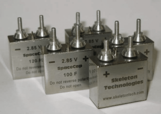
Different test campaigns were carried out, in order to assess the influence of the specific CDC type, the electrode thickness, the separator materials, and the specific DC-current and ambient temperature. SpaceCap prototypes were designed with prismatic shape. The casing was made from stainless steel (SS304), with dimensions 27×32×16 mm (H×L×W) and wall-thickness of 0.3mm, which assures the mechanical strength of the capacitor and possibly gives better
radiation resistance compared to aluminium casings (see Fig. 1).

As a result of optimizing the selection of these parameters, it was concluded that the HE prototypes developed possessed an energy density of 5.8 kW/kg, which exceeded by ~50% the capabilities of the commercially available devices with similar energy capacity at the time of the study. The HP prototypes developed possessed a power density of ~44.9kW/kg, which exceeded by 4 times the power density of the commercially available devices with similar energy capacity at the time of the study. This research enabled SKELETON to develop CDC synthesis and post-treatment research for achieving higher power and energy densities. It was also possible to control the temperature behaviour of the CDC-based electrode.
The next CDC supercapacitor-related R&D activity with ESA had the aim of elevating the technology readiness level (TRL) of the ~100F SpaceCaps prototypes designed for high-power (HP) capabilities. In order to achieve this target, the SpaceCap incorporated a relatively high level of graphitization of the CDC material using relatively high reaction temperatures. A second objective was to design and manufacture two Electro-mechanical demonstrators (EMM1=”alpha” and EMM2=”beta”) of the SpaceCap Module (SCM).
63 SpaceCap units were submitted to a set of tests, taking as a reference the F4 chart of the draft ESCC Generic Specification “Supercapacitors, EDLC”, including mechanical testing (vibration and shock), thermal shock, electrical measurements, life test and life cycle test. The test results supported the objective of achieving power and energy densities beyond the state-of-the-art in the supercapacitor domain. However, it also revealed several weaknesses:
- Relatively large variance in electrical performance: ~20% for capacitance, ~25% for ESR
- High variance in life test performance and life test failures: 2 out of 15 cells failed the voltage hold tests, 3 out of 6 cells did not pass the life cycle test. The ones that passed the test showed a variance of ~40%.
The SpaceCap Module (SCM) was developed and designed for space applications incorporating SpaceCaps “tuned” for power rather than higher energy density through relatively high level of graphitization by using higher reaction temperatures. Two SCM were manufactured and submitted to a test campaign, taking as a reference the ECSS-E-ST-10-03C: environmental, vibration and shock, physical properties and initial and final quality control tests.
The mechanical testing on the engineering model was achieved without failures, which has proven that the overall design and the balancing circuitry is ruggedized.
References [4]
GRAPHENE SUPERCAPACITORS
Graphene-base materials as electrodes for supercapacitors Graphene is a thin layer of pure carbon, tightly packed and bonded together in a hexagonal honeycomb lattice. This material possesses a quite unique set of characteristics: it is one-atom thick, it is the best electrical conductor known up
to date and has light-weight and elastic properties, as well as relatively high mechanical strength. Graphene is often suggested as a replacement for carbon-activated supercapacitors. Research carried out in the last decade has identified graphene-like layers as a potentially interesting electrode material, due to the highest existing surface-over-mass ratio, high conductivity and high chemical stability. For instance, it has been demonstrated that nanosheet carbon electrodes can reach specific energy above 100 kWh/kg. Moreover the combination of graphene and metal oxide for combining EDLC and pseudo-capacitance has demonstrated a specific energy above 98 kWh/kg at the laboratory scale. However the manufacturing of graphene-based electrodes and their long-term reliability were facing several challenges. Most of the processing methods for graphene-based electrodes relied on dispersion of graphene or other two-dimensional (2D) materials in solution and coating on the current collector material, with organic spacer usually allowing the separation of the 2D layers. With this method, the electrical contact between the collector and the graphene layers was an issue. Moreover the restacking of 2D layers was a strong risk for the long-term stability of the electrodes.
A possible solution could be to grow the graphene layers directly on the current collector, which could allow a direct electrical contact with the current collector and an enhanced stability, due to the absence of spacer material. Such a growth method should however be compatible with a commercial substrate, while usual growth of graphene layers was performed on ultra-smooth metal layers. Moreover the method should be compatible with large-scale production, ideally compatible with the roll-to-roll manufacturing process used for metal foils.
This R&D ESA activity [13] aimed at investigating the challenges of processing graphene-like layers directly on electrode material, and in particular on thin commercial copper foils, using the chemical vapour deposition method. Moreover the realized electrodes were tested by cyclic voltammetry in the single-electrode configuration, as well as in the two-electrode configuration, which is representative of a real supercapacitor device.
The activity successfully demonstrated the growth of graphene-like layers on two types of commercial copper foil, a standard foil from Goodfellow (250 μm thick), and an ultra-thin foil from Circuit Foil (18 μm thick). The growth was performed using C2H2 as carbon precursor, and H2 to avoid oxidation. Both substrates could thus be successfully coated with graphene-like layers, mainly made of multi-layer graphene, as demonstrated by Raman spectroscopy. Both substrates also showed a good graphene coverage despite their initial roughness. A slightly higher graphene quality of the layers grown on Circuit Foil’s substrates was detected, with the demonstration of single-layer graphene deposited after exposing the substrate to H2 without C2H2, which was not observed for Goodfellow’s substrates.
However, it was observed that the deposited graphene layers formed a flat coating. This was detrimental for the use of the afore mentioned electrodes for supercapacitors, since they showed an enhanced specific area. This absence of enhancement of the specific area was confirmed by cyclic voltammetry in the single-electrode and the two-electrodes configurations. In order to investigate the growth of graphene-like electrodes with larger specific area, the growth
conditions were changed, especially the reduction step, the growth time, and the inert gas during cooling of the substrate. The main result was that no improvement of the specific area with the growth time was observed, but only a degradation of the graphene layers. On Goddfellow’s substrates, the deposited carbon material also showed a relatively large number of irregularities. A plausible explanation was the low permeability of graphene layers. As soon as the first few layers were deposited, the precursors could not reach the copper surface anymore. Then they could not use the metal surface as
catalyst, and the precursor was decomposed on the surface rather that reacting to form graphene.
The graphene-coated copper foils were tested as electrodes in the single-electrode and two-electrodes configurations, using Na2SO4 and H2SO4 respectively, as neutral and acidic electrolytes. No increase of the capacitance, and thus of the specific area, was observed from bare copper to graphene-coated copper. This confirmed the flat coverage of the substrate. Interestingly, the bare copper electrodes showed a peak at the first cycle due to the reduction of Cu2O to Cu, which was not observed in the graphene-coated electrodes. This corroborated the low permeability of graphene deposited on copper, which then acted as corrosion protective layer.
References [13]
De-risk assessment of a graphene enabled supercapacitors cell (GRACE)
The de-risk GRACE activity was deployed to develop a supercapacitor cell with proven capabilities of increased specific energy and life cycle while maintaining satisfactory power density by exploiting the promising properties of graphene. Furthermore, to meet space application requirements and maintain clear competitive advantages as a product, the goal was to achieve broad operating conditions for the cell (-40 to 70ºC).
The main objective of GRACE was to select, manufacture, test and benchmark graphene-based supercapacitor electrodes by testing different graphene commercially available products in different compositions, as well as establishing a supercapacitor cell manufacturing process with all the necessary QA/PA measures. By employing material optimization steps, the initially set objectives were achieved, and graphene-based electrodes with promising capacitance performance were developed and tested. Also, further optimization steps were employed on the development of a supercapacitor manufacturing process by testing different approaches and materials on the overall design of the cell.
During the activity, the parameters and all the design aspects that finalized during electrode and supercapacitor cell optimization were applied for the development of large scale of cells and a testing protocol applied for their performance evaluation. The testing protocol was based on the IEC (International Electrotechnical Commission) protocol that is used for the characterization of commercial supercapacitor cells. Several trials were performed on large scale pouch cells. Finally, the pouch cells were tested under the designed test protocol.

The results on electrode level validated the prospective use of the material in an actual supercapacitor. More specifically, the best formulations during the electrode optimization phase exhibited specific capacitances of 323 F/g and 356 F/g by using high content of graphene nanoplatelets in combination with other materials. These values measured indicate a significant improvement compared to commercial activated carbon, which presented a maximum specific capacitance of 120 F/g.
The results in large scale pouch cell level indicated a transfer ratio of the electrode property around ~45%. The cells were designed to perform approximately ~80 F. However, the final results showed a maximum capacitance value of 37 F. The targeted value of energy density was achieved ( ~30 Wh/kg, so higher than 10 Wh/kg) which was the most demanding property in the supercapacitor industry. The life cycle of the cells was lower than expected. A more comprehensive study shall be performed on the combination and suitable pairing of electrolyte/electrode system.
In general, the development of the activity starting with the development of high-performance graphene-based supercapacitor electrodes and transferring them in the structure of a pouch cell was successful in the limits of the de-risk GRACE activity. The specific capacitance values that achieved during the activity were very promising (323 F/g and 356 F/g) for the future. The electrodes were successfully integrated into a process for the production of pouch cells.
Upon the completion of the de-risk GRACE activity the TRL of technology was 4. The developed graphene electrodes passed through analytical and experimental critical characteristic proof of concept, and transferred to the formation of breadboard prototypes were tested for functional verification in laboratory environment.
References [1]
SPACE QUALIFICATION AND APPLICATIONS
GENERIC SPACE QUALIFICATION OF 10F NESSCAP SUPERCAPACITORS
At component level, the objective of the activity was to perform a test campaign on the ESHSR-0010C0-002R7UC supercapacitor (10F) manufactured by Nesscap to prepare the entry of this part into the EPPL part 2. Therefore, the component already existed and no specific development was requested on the part itself. No modifications were foreseen on the commercial grade product. The purpose of the activity was to make it available at space grade.
At unit level, the objective of the activity was to develop a supercapacitor bank, called BOSC (Bank Of Supercapacitors).
This unit was composed of supercapacitors placed in series and parallel in order to achieve the requested capacitance and voltage ranges. The configuration of the BOSC was 34 components in series and 3 strings in parallel (see Fig.3). The parts selected were the same as for the component level: ESHSR-0010C0-002R7UC supercapacitor from NESSCAP. A passive balancing system was implemented in order to make sure the cells voltages remained in the safe areas. Some test points were foreseen in order to check the correct functioning of this function. Finally, some thermistors were attached to the unit in order to monitor the thermal response of the unit.

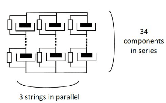

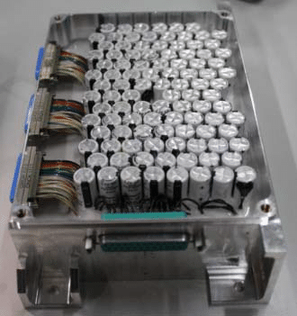
The design requirements were set to cover several bus voltages and capacitance needs. Also, the minimum application voltage was 28V. Since the BOSC voltage drops during discharge (unlike batteries), the maximum BOSC voltage was to be almost twice as large. The minimum capacitance was considered for a modular design. The final design needed to be robust enough to withstand the loss of one supercapacitor. The number of capacitors in parallel should not be relatively low. So three strings in parallel were chosen as a compromise between robustness and modularity (see Fig.3). On top of that, the unit was designed to allow for mechanical and electrical modularity in order to adjust the capacitance at system level as a function of the mission needs.
At component level, 3000 samples were procured and submitted to screening, in order to rule out infant mortality. The samples were submitted to a qualification test campaign, taking as a reference the chart F4 in ESCC standards, including vacuum testing, vibration and shock, fast temperature transient tests, seal tests and calendar life tests as well as life cycle tests.
The testing at unit level included mechanical inspections (dimensions, mass, flatness and roughness), electrical inspections (bonding, electrical continuity, isolation and electrical characterization), vibration and shock, thermal vacuum tests, and long life test.
The result of the space grade qualification of the Nesscap supercapacitor ESHSR-0010C0-002R7UC was successful. A large amount of qualification tests were performed and all the electrical and mechanical parameters of this supercapacitor stayed in the specified range.
The assembly of these supercapacitors in a Bank Of SuperCapacitors (BOSC) was electrically, mechanically and thermally designed and confirmed by analysis. Then a complete space grade qualification campaign was performed. All the tests were completed and successful.
The major drawback for the supercapacitor was a calendar deterministic ageing which depends on the temperature and the charging voltage. This was also the case of batteries. It could be maintained in the expected levels by applying derating in voltage and limiting the use temperature to 40°C.
The Nesscap 10F at component and BOSC levels were ready for flight, the TRL reached after this activity was 6.
References [14]
SUPERCAPACITOR FOR LAUNCHER APPLICATIONS
Historically in launchers, and in particular for ARIANE, electrical power supply was not a big issue as missions were very short (less than one hour), consisting essentially of Geostationary Transfer Orbits (GTO). As a result, power sources technologies remained unchanged for a long time, from Ariane 1 to Ariane 5: Ag/Zn batteries for functional avionics, hydraulics thrust vector control and NiCd batteries for pyrotechnical orders and safeguard.
Nowadays the scope of missions as well as their duration was becoming larger and larger, varying from 1 hr (GTO) to 7 hours (GTO+, Medium Earth Orbit). Several functions of the launcher Ariane 6 were electrified, thus changing dramatically the energy and power requirements. In addition, lithium-ion technology batteries were developed and qualified for Ariane 6.
Even if supercapacitors are not currently used in launchers, they hold a tremendous potential that has been investigated for about 10 years, mostly because of their ability to charge and discharge instantly and their very high power density, which fits with power supply needs requiring a high peak power demand. Indeed, the use of supercapacitors, in replacement or in combination of batteries, will enable to obtain interesting mass savings.
Vertically Aligned Carbon Nanotubes (VACNT) electrode materials, developed by NawaTechnologies were selected for this ESA R&D activity [1], due to the fact that VACNT supercapacitors performances were expected to be better than classical carbon supercapacitors, in terms of specific power and energy capabilities. This new strength, added to their high power capability and thermal efficiency has the potential to create the ultimate energy storage product.
The need for testing the technology in the high vibration environment was defined and a representative Bank of Supercapacitors (BOSC) composed of 11 cells provided by NAWATechnologies was built. The packaging has been tailored to the pouch cell. It allowed to offer a good interface to the cell and prevented it from unnecessary damages.
After integration of the supercapacitor cells, tests were carried out on the BOSC assembly and on a single spare cell.
A VACNT representative cell in mass and dimensions of the future cell was provided in order to perform vibration testing. The vibration test objective was to test the packaging interfacing and the VACNT supercapacitor pouch cell at launch loads. The test was successful. In order to encapsulate the pouch cell, stacks were designed that had to be light but strong enough to sustain launch environmental loads. Total mass of one single stack including cell.
General objectives of the tests were to demonstrate that the cells and the BOSC could survive and work properly as required in the specific pyrotechnical application under stringent environmental conditions of launch and space. Specific objectives of electrical tests were to measure and qualify the electrochemical performances of the cell during different conditions. Such tests let to follow the ageing of cells during their use and their storage. The functional tests were performed to ensure that the supercapacitor cells were compliant with the technical requirements specification. Electrical
and environmental tests were conducted at cell and BOSC levels in order to detect issues at those different levels.
Preliminary electrical and environmental tests were conducted in preliminary prototype VACNT cell and associated single stack structure. The outcomes of the tests were that structure held well the pouch cell during the environmental loads, and moreover that no electrical performance degradation was observed even after stack reached vacuum level. Indeed, the electrical measures showed that the properties were kept within variation of test benches measurement errors, with a slight increase in capacitance to be noted, supposedly due to the effect of forming the cycling had on the cell. Visual and Low Sine vibrational inspections showed no evidence of structural degradation, while providing characteristics of the packaging, as its first natural frequency at 600 Hz, its damping factor of 3.8% and its quality factor Q of 13.3. These last two numbers showed that the glue interface of the BOSC played a non-negligible role in its structural integrity, as the usual damping factor for metals stayed within 2 %. The high natural frequency of 600 Hz showed that the design was rigid enough to avoid a too large response during the sinusoidal tests that went up to 375 Hz. However, the damping caused by the glue and cell interfaces allowed the initiation of the response at 100 Hz already. This would need to be monitored to limit the stress and the eventual fatigue in larger BOSC integrations. The stack reached the level of vacuum of 10-5 Torr without issue. Despite some grid noise at 50Hz, electrical tests showed that performance of the cell stayed stable after these two tests.
Functional and life tests were performed on the cell and on the BOSC, including vacuum test for the BOSC. The electrical tests performed on cell1 show that al tests performed have not degraded the initial electrical performance of the cell.

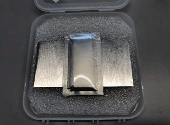

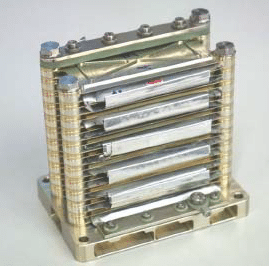
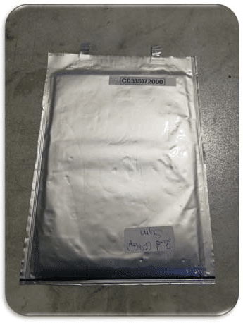
Fig.5 A VACNT pouch on the left of the image (manufactured by Nawa Technologies) and ALMATECH Bank of Supercapacitors on the right
The BOSC was functional until the vacuum test. However, the electrical performance of the BOSC was not optimal. In contrast, no important degradation was observed on the BOSC electrical performances with respect to previous values. Nevertheless, due to test device limitation and the BOSC having only two cells, the test could not be considered relevant. During the vacuum test, the BOSC had a leak of solvent even if no visual damage was observed. The target pressure of 10-5mbar could not be reached and Almatech decided to abort the test after 7h where pressure did not fall under 10-4mbar due to leakage of chemical substances outside the supercapacitor cell. The micro-leaks were confirmed by the loss of mass (2.27g) and the decrease in electrical performances. The electrical tests results could be observed in a row starting with FT6 RT where equivalent resistivity increased significantly and capacitance dropped down significantly.
The VACNTs supercapacitors technology developed by NawaTechnologies presented some limitations in terms of electrical performances for the aimed application which lead to a TRL limited to level 4 instead of 7, as planned at the beginning of this activity:
- Capacitance of the cells of the order of magnitude of 60F, versus the 200F expected
- Specific energy at cell level of the order of magnitude of 4.80Wh/kg, versus the 15 Wh/kg expected.
Furthermore, the VACNTs supercapacitors technology developed by NawaTechnologies presented some limitations in terms of cell design:
- Lack of electrical performances at temperature of -30°C
- Poor behaviour of the cells assembled in BOSC under vacuum conditions.
References [15]
DISCUSSION & CONCLUSIONS
CHALLENGES TO OVERCOME
CDC SpaceCaps & SpaceCap Modules
- A thorough rethink of the SpaceCap design, manufacturing and assembly process should be taken in future R&D activities in order to optimise the performance of the SpaceCap.
- To be able to produce and manufacture a lighter design in mass of the SpaceCap Module in the future, with tighter dimension tolerances.
References [4]
Graphene-based materials as electrodes for supercapacitors
- The major limitation of the growth method towards electrodes for supercapacitors was the obtained morphology of graphene flakes. Possible solutions might be to produce electrodes with higher specific area or a highly structured substrate. The improvement of the performance of supercapacitors can also go in the direction of using the pseudo-capacitance effect.
- Further development is necessary to optimize the operation of the produced pouch cells where the identical combination of electrolyte and pouch cell materials in general with the produced electrodes should be studied.
References [13]
De-risk assessment of a graphene enabled supercapacitors cell (GRACE)
- Further supercapacitor cell design and manufacturing process optimization is needed in order to maximize the cell performance.
- The final cell design incorporating the graphene electrodes must maintain very low internal resistance and exhibit an energy density higher than 10 Wh/kg.
- Design and development of a single supercapacitor bank module that incorporates the developed cells is needed.
- A graphene-based supercapacitor bank breadboard should be manufactured and initially tested to prove the technology capabilities, incorporating appropriate Management Systems to ensure controlled and safe operation.
References [1]
Generic space qualification of 10F Nesscap supercapacitors
- R&T activities are deemed necessary in order to improve power density and high temperature lifetime.
- Future approval and publication of the related ESCC generic and detail specifications is needed.
References [14]
Supercapacitors for launcher applications
- Cell material and electrolytes enhancement is required in order to improve the electrochemical performances.
- Leak tightness under vacuum needs to be improved.
- Improvement of the cell characterization process is indispensable.
- The BOSC must be validated including 12 functional cells in order to reach an operating voltage of 32V.
- Vibration tests need to be conducted on the BOSC.
References [15]
SUMMARY AND CONCLUSIONS
R&D activities to develop supercapacitors lead by ESA have demonstrated a number of achievements and improvements in the developing, manufacturing and qualification for space applications.
Two more R&D activities on supercapacitors are intended to be published soon:
- Optimization and space qualification of CDC supercapacitor cells and supercapacitor module.
- Graphene enabled supercapacitors cell optimisation and bank system.
REFERENCES
[1] Graphene Enabled Supercapacitors Cell, ESA-GRACE-FR, Pleione Energy, 2010
[2] Supercapacitors: Materials, Systems, and Applications, Francois Benguin, Orleans, Ed Wiley, 2013
[3] Evaluation and qualification of commercial off-the-shelf supercapacitors for space applications, 2nd Space Passive Component Days (SPCD), 2016
[4] High Power and Energy Density Ultracapacitors in space environment, Mati Arulepp, Jaan Leis, Skeleton Technologies, Estonia; SpaceCap and SpaceCap modules Final Reports
[5] High power density modular electric power system for aerospace applications, Scott Steffan, Gregory Semrau, Moog Inc, Space and Defense Group, New York (USA)
[6] Resistojet thruster with supercapacitor power source – design and experimental research,
[7] Supercapacitor energy storage for micro-satellites, T. Shimizu, C. Underwood, Surrey Space Centre, University of Surrey, UK.
[8] Printing Porous Carbon Aerogels for Low Temperature Supercapacitors, Jennifer Q. Lu, University of California, Merced, USA, Yat Li, University of California, and colleagues Santa Cruz, California (USA).
[9] In-orbit feasibility demonstration of supercapacitors for space applications, Jesús González Llorente, Sergio Arboleda University, Bogotá (Colombia), Kei-Ichi Okuyama and colleagues, Kyushu Institute of Technology (Japan)
[10] High power and energy density ultracapacitors, Mati Arulepp, Jaan Leis, Skeletontech, Tartu, Estonia.
[11] Interdigitated MEMS supercapacitor for powering heart pacemaker, Hafzaliza Erny Zainal Abidin and colleagues, Institute of Microengineering and Nanoelectronics (INEN), National University of Malaysia, Selangor (Malaysia)
[12] SafeCap: Ionic liquids Supercapacitor, Marc Zimmermann, Carole Buffry, Hutchinson Research Centre, Chalette-Sur-Loing, France.
[13] Graphene-based materials as electrodes for supercapacitors, Final Report, Luxembourg Institute of Science and Technology (LIST)
[14] Generic Space Qualification of 10F Nesscap Supercapacitors, Final Report, AIRBUS (France), EGGO (Czech Republic)
[15] Supercapacitor for launcher applications, Final Report, ALMATECH (Switzerland), Nawa Technologies (France), Ariane Group (France)

