
Design of maintenance-free battery-less microcontrollers enabled by tantalum capacitors and supercapacitors are discussed in a technical paper written by Ron Demcko, Daniel West and Ashley Stanziola, KYOCERA AVX Components Corporation.
Introduction
Ultra-low-power microcontroller families now exist with such low power requirements that they can be powered by energy harvesting rather than battery-operated or conventional mains. These powerful MCUs enable maintenance-free control systems in applications ranging from structure/soil/water/air monitoring applications to industrial point controllers (such as smart faucets) to wearable electronics, location tracking, and even BLE beacons.
Ultra-low-power microcontroller families now exist with such low power requirements that they can be powered by energy harvesting rather than battery-operated or conventional mains. These powerful MCUs enable maintenance-free control systems in applications ranging from structure/soil/water/air monitoring applications to industrial point controllers (such as smart faucets) to wearable electronics, location tracking, and even BLE beacons. Examples of end applications such as battery-less Air Quality Monitoring and Battery-less LoRaWAN Remote Sensors are below:
Battery-less Air Quality Monitoring:
Visit Link
Battery-less LoRaWAN Remote Sensor:
Visit link
This paper is based around a Renesas Evaluation board RE01-1500KB that utilizes an RE Family ultra-low power MCU built using Silicon On Thin Buried Oxide Technology – SOTBTM.
The low-power MCU is powered by a modest capacitance value Tantalum capacitor which provides a start-up voltage function. Supercapacitors provide longer-term processing power. Once the charge depletes from the supercapacitor, the Tantalum start-up capacitor provides voltage and powers the MCU in a maintenance state until the supercapacitor becomes fully charged and processing functionality returns to a high level. The process repeatedly loops until the energy harvesting power source stops. At that point, the MCU shuts down and awaits the Tantalum capacitor to flag the MCU that the energy harvesting power source has returned.
The start-up capacitor charges, the MCU is prepared for full processing power to be provided by the supercapacitor, then the tantalum / supercapacitor process repeats. This evaluation documents tantalum capacitor and supercapacitor device characteristics and in-circuit performance.
Introduction
Energy harvesting has successfully powered less complicated ICs such as IoT modules through small, cost-effective, efficient PMICs matched to power inherently low power IoT loads1. Semiconductor technology advances have continued, and it is now important to recognize the progress in low-power complex ICs. In particular, low-power MCUs capable of operating through small, low-cost energy harvesting/energy scavenging sources. An industry-leading device is the Renesas RE microcontroller family, where SOTBTM Process Technology enables low power use.
SOTBTM technology enables MCUs to have Ultra-low power consumption in both active and standby mode. An example of the typical performance of a 32bit CPU Arm®Cortex®-M core shows its high-speed operation could be up to 64MHz at 1.62V. Typical current consumption of this family could be:
- 25uA/MHz active (internal LDO mode)
- 12uA/MHz (external DCDC mode)
- 400nA Standby with 32KB Ram retention
- 100nA Deep Standby
Low current consumption at low voltages is why this family of MCUs has the option for battery-less – energy harvesting power sources. A comparison of just how far SOTBTM reduces power consumption relative to other competing process technologies2 is shown in Figure 1.

SOTBTM exhibits significant performance advantages over FDSOI processed devices. Further explanation of the RE01 microcontroller energy harvesting operation shows that each RE01 contains an Energy Harvesting Controller – EHC. A link to the devices landing page can be found here.
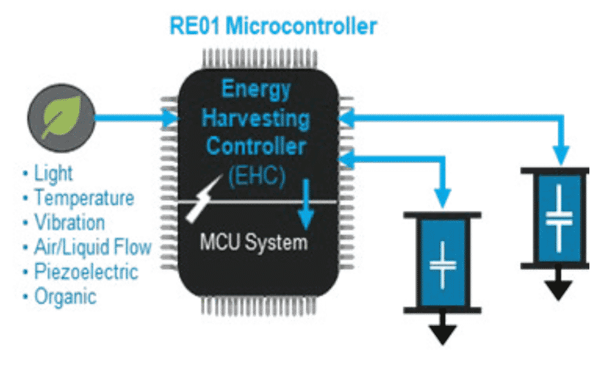
The EHC accepts energy generated from solar, piezo, Thermal Electric Generators (TEGs), micro turbine, pressure – etc. It then manages harvested power by channeling and balancing energy through one of the two capacitors to powering the MCU. To achieve this, the EHC contains sub-level PMIC, charge controller, and power management functionality. On a more functional basis, the EHC can be viewed in many ways. It provides functions as basic as reverse current protection. However, it provides more complex functionality when viewed as the direct energy-harvesting link—controlling voltage regulation, quick start-up control, autonomous and reliable start-up sequencing, start-up current control, energy storage charge management selection of capacitor power sources.
The configuration of an energy powered RE01 MCU is shown in Figure 2. Temporary energy storage is provided by a tantalum capacitor and secondary storage is provided by much larger capacitance value supercapacitor.
Selection of Start-up and Storage Capacitors
As previously mentioned, when the RE01 MCU is configured to operate from an energy harvesting power source, the EHC relies upon a start-up capacitor, C-SU, to charge quickly and provide the low-level power for MCU power up initiation. Long-term power comes from batteries (or in the case of this study – supercapacitors).
Figure 3 outlines the relationship between power management states and the EHC interaction with C-SU and the storage supercapacitors. We will concentrate on powering the MCU from voltage stored in a smaller capacitor (C-SU) and maintaining MCU operation with voltage stored in the large supercapacitor.
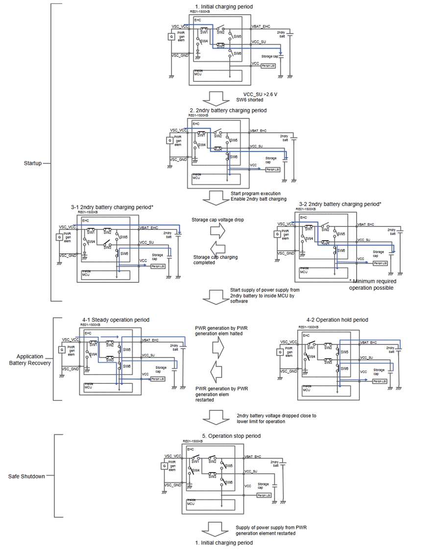
To summarize:
Once energy harvesting power is apparent, the EHC charges the start-up capacitor C-SU. When C-SU charges to 3.0 volts – power on reset initiates at the MCU, and the secondary supercapacitor’s charging starts.
While the supercapacitor is charging, C-SU power is being used by the EHC to initiate operations of various stages of the MCU. Once the supercapacitor is charged, the MCU power transitions to the supercapacitors for longer-term operation. During that time, C-SU is recharged and ready to maintain various active computing functions while the supercapacitors are isolated from the MCU by the EHC and recharged. Once the supercapacitors are recharged, the MCU power transfers from C-SU to the supercapacitors. At that point, the MCU gains more powerful functionality.
The whole process continues in a loop until the energy harvesting power source is no longer available and the system shuts down. At that point, the MCU waits for C-SU to get charged up & the use cycle continues. This study concentrates on the selection and operating characteristics of C-SU and the supercapacitors.
Microcontroller Capacitor Performance Requirements
Performance Requirements & Characteristics of C-S
The start-up capacitor C-SU is required to:
- Operate from -40°C to + 85°C and provide 100 to 150μF of capacitance across temperature
- Exhibit Low ESR due to charge currents from various charge sources
- Exhibit low leakage current (high insulation resistance) to reduce standby currents
- Use little board area
- Have the ability to be processed with standard PCB processing
- Provide high reliability
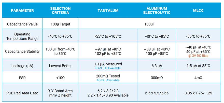
There are three capacitor technology options available for a 100 to 150μF storage capacitor used at ~ 3V. A comparison of Tantalum, Aluminum Electrolytic and Multi-Layer Ceramic Capacitor (MLCC) technologies is shown in table 1. This table shows that Tantalum capacitor technology meets the requirements of a start-up charge retention capacitor. Tantalum capacitors offer significant advantages over high CV MLCCs as well as Aluminum electrolytic capacitors.
Tantalum Capacitors Advantages
Tantalums do not exhibit capacitance instability due to DC bias, operating temperature, or age. This is a major disadvantage for MLCCs since a 100μF rated part may actually demonstrate 20 or 30 μF properties while in application. High capacitance value MLCCs exhibit extreme capacitance instability 3. Capacitance instability plus large physical size are the main reasons that MLCCs are not recommended for use as start-up capacitors.
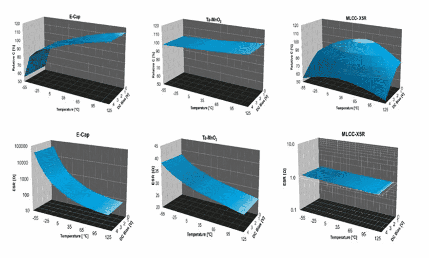
Aluminum Electrolytics offer more stability than MLCCs, but that comes at a price of increased size, weight, and potentially much less reliability. Although Aluminum Electrolytic capacitors exhibit large capacitance values in small case sizes their electrical properties vary with temperature. A comparison of Aluminum Electrolytic, Tantalum and MLCC stability is shown in figure 4.
Start-up Capacitor (C-SU) Summary
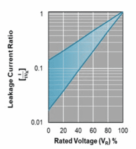
The capacitor chosen for C-SU is KYOCERA AVX P/N: TPSC107K010R0200. This particular series of capacitors is AEC Q200 automotive grade qualified and is available in 14 different case sizes with voltage ratings from 2.5 to 50V and values from 0.15 μF to 1500 μF. Tantalum capacitors are available in numerous case styles, including true EIA case size SMT chips and high-density undertab styles. Tantalum capacitors offer a wide range of products available with the smallest 0402 footprint and the lowest height sub 1mm profile solution. Furthermore, options exist for designers to further reduce the in-circuit leakage by derating the capacitors’ voltage rating. A graph depicting the extent to which leakage currents reduce from derating is shown in figure 5.
Performance Requirements & Characteristics of C-bulk
Supercapacitors are generally recognized as a low cost alternative to a rechargeable battery when hundreds of thousands to ~ million charge/discharge cycles are needed. Supercapacitors multiple form factors contribute to the ease of implementation in end systems. Multiple options exist for supercapacitor selection (see table 2 comparison) and the end device selected depends upon the desired applications run time and package characteristics of the supercapacitor.
This study is comprised of two test cases:
- Two ultra-miniature radial supercapacitors connected in series to create a 0.5F, 5.4V storage device. The individual capacitors used were KYOCERA AVX P/N: SCCQ12B105PRB.
- A miniature packaged module was selected to create a much larger storage capacitance which was intended to power the load for a longer time. The value chosen was 1F at 5V, KYOCERA AVX P/N: SCMR18C105PRBA0.
Radial Can Discrete Supercapacitors
The ultra-miniature devices were chosen for this study since these devices offer designers maximum flexibility through:
- Multiple product series available
- Multiple voltage offerings
- Ten different case sizes
- Highest number of capacitance values available
Radial can parts are commonly used in single configuration for lower voltage designs or multiple cans (as the case for this study) can be configured to obtain the correct voltage/energy for higher voltage loads. Multiple cans can be balanced via active or passive methods. Supercapacitor balancing is needed to ensure long life for multiple Supercapacitors used in series. Balancing each Supercapacitor prevents damage from over-voltage to other Supercapacitors in the stack.
Since passive balancing is accomplished with a resistor, it has the advantage of being the cheapest, smallest, and easiest to use. However, the big disadvantage from passive balancing is that power is dissipated through the balancing resistor, which reduces efficiency. Active semiconductor balancing is the most efficient and exacting method. However, its costs are more significant. The size required for active balance solutions varies greatly based upon the number of cells in need of balancing as well as the size of cell/semiconductor type’s used in balancing.
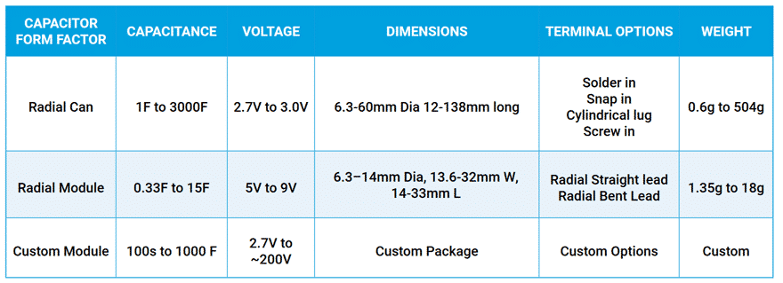
Radial Modular Package
The miniature radial module was selected to study as a test example for extending CPU run time. Radial modular packages are manufactured by connecting two radial can capacitors in series and packaging them into a ‘module’. These packages offer maximum efficiency of package density and a higher voltage.
Applications with higher voltage batteries often find these packages very beneficial for simplifying design. As discussed previously, radial modules can be balanced or unbalanced and have the options for hard-shell or heat-shrink packaging depending upon the end user’s need for enhanced reliability.
Supercapacitor Reliability
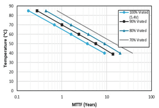
Regardless of the specific package configuration, supercapacitors need to be properly de-rated to achieve reliable long-term operation. Previous work by DeRose et al.4 shows that supercapacitor reliability is a function of applied voltage and use temperature. In their work, various ACN chemistry supercapacitors were subjected to a matrix test where voltage, temperature, and humidity stress levels were varied while the DUTs capacitance and ESR were measured to determine stress effects.
MTTF (in years) vs. applied voltage and applied temperature was tested. Figure 6 shows a series of graphs with the results from the test data. These graphs indicate that the expected life more than doubles for every 10°C lower than operating temperature. Life doubles again for every reduction of 0.1V lower than operating voltage.
SuperCapacitor Parameters
Three of the most important electrical characteristics of supercapacitors are capacitance, ESR, and leakage current. The capacitance of a supercapacitor is stable from 0°C to 40°C [approximately -10%]. Since capacitance values are very large ~3 Farads/cc, capacitance drop can be substantial. Due to this, capacitance-temperature effects are more of a reliability concern, opposed to a minor drop in capacitance. The lifetime of a supercapacitor is extended an order of magnitude for every 10°C reduction in operating temperature, as mentioned previously.
The ESR of supercapacitors can be exceptionally low (single digit milliohm values) based upon capacitance value and case size of the selected device. ESR values increase with decreasing temperature. At 0°C, values are typically 125% of the 25°C value and increase to ~ 225% at ~ -40°C.
Leakage currents also vary by capacitance value, voltage rating, packaging style and temperature. Temperature effects impact leakage by decreasing the 45°C value to near zero at ~-40°C and increasing to ~650% of the 45°C value at ~85°C. Generally speaking the supercapacitors performance at temperature extremes greatly eclipses that of a battery over the medium to long haul.
Supercapacitor voltage ratings are commonly ~2.7V per cell. They can be stacked in series to create higher voltage operating stacks. The end user can perform stacking or small stacked modules of all sizes that are available from manufacturers. The wide availability of power management ICs with cell balancing tends to dictate the economics of single cells configured by end users.

A general comparison of supercapacitor to Li-Ion battery comparison is shown in table 3. Supercapacitors operating temperatures align with the intended use range of the RE01. Further, cell voltages are adequate; the cycled life exceeds that of Li-Ion batteries. Supercapacitors cycle ability is most in line with high frequency charge-discharge applications such as repeated cycle energy harvesting for an MCU.
Testing and Summary
C-SU Performance
To demonstrate the use of a Tantalum start-up capacitor (C-SU = KYOCERA AVX Part number: TPSC107K010R0200), two cases were created. C-SU used in conjunction with a small ultra-miniature supercapacitor stack and a larger capacitance value, yet, for the purpose of extended run time, still miniature supercapacitor stack. In all test cases the RE01 evaluation board was put into a Demo mode/loop.
A link to the easy to use Renesas evaluation kit which was used to generate test results of this paper follows: Renesas Evaluation Kit
*It should be noted that Renesas offers another kit, which may have even more applicability to ultra low power IoT applications. Potential end users should also consider the use of this device through evaluation board EK-RE01 256KB.*
The RE01 256KB version can also be powered through tantalum and supercapacitor combination and shows the wide range of end products and applications capable of utilizing such power schemes. A link to the RE01 256KB evaluation board follows: RE01 256KB.
The purpose of this test was to confirm that a tantalum capacitor can provide exceptional start-up role C-SU and to show the length of operation provided by two different sized supercapacitors (ultraminiature & miniature test cases). Testing was easily accomplished through the evaluation kit’s detailed supporting documents and its user community. Further, added information about the periphery to the RE01 core is very well supported by the ECO SYSTEM partners Renesas has created. A link to supporting partners follows: Supporting Partners.
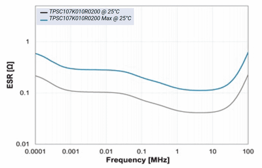
The TPSC107K010R0200 has attractive dimensions for use in high density circuitry. It occupies a board area of 19.2 mm². Its height is 2.6 mm and has a total volume of 0.05 cc. Further tantalum capacitors are very light relative to other technology alternatives. The TPSC107K010R0200 weight is roughly 170 mg. The devices ESR is low and stable as shown in simulation – Figure 7. Size, stability, and reliability make this capacitor the ideal start-up capacitor for all LP & ULP chipsets.
The TPSC107K010R0200 performance exhibited expected behavior that was critical to the RE01 board operation. While using TPSC107K010R0200 the power was properly toggled and demonstrated the desirable performance during the execution of the normal demo mode of the RE01 1500KB evaluation board. From an energy point of view, the demo execution mode consisted of C-SU charge, power source transition to C-bulk, C-SU secondary charge/maintenance, power transition to C-SU, supercapacitor recharge and system shut down cycles.
C-Bulk (Supercapacitor) Performance
As indicated previously, two supercapacitor test cases were chosen to provide data representative of an end user building their own custom radial stack or choosing a standard 5.4V module. Run time results will vary from numbers reported since end users will have significantly different code and execution cycles than demo mode software.
Test 1:
Consisted of connecting 2 ultra-miniature radial can Supercapacitors (P/N: SCCQ12B105PRB) in series to obtain a 0.5F 5.4V rated stack.
Test 2:
Consisted of a miniature radial module (P/N: SCMR18C105PRBA0) to provide 1F at 5.4V.
A specification comparison between the two supercapacitor test cases is shown in table 4. Results show that larger bulk capacitance stores more energy and therefore powers the semiconductor longer, as shown in the charge/discharge cycles of figure 8. Designers have a significant number of options to design larger or smaller version bulk capacitance banks given the many different capacitance values and form factors supercapacitors come in.


Summary
High-performance ultra-low-power MCUs are so energy efficient that they may be effectively be powered by energy harvesting generators powering capacitors. These ICs have an extensive range of applications in every end sector. The devices will provide massive efficiency gains in control and monitoring of applications.
A common architecture for ULP ICs is to have a start-up capacitor and bulk capacitor working in conjunction to provide power to initialize and sustain long-term device operation. Tantalum capacitors exhibit high levels of capacitance stability and low loss in small, lightweight packages. These devices are available in consumer, automotive, COTS, and high-reliability quality grades and are the ideal start-up capacitor.
SuperCapacitors are used for long-term power and are available in radial can or module packages. The two different package types provide high levels of flexibility for designers to optimize physical package size and run the end design characteristics. Long-term, reliable storage capacitors enable high-performance ULP MCUs to operate in set and forget applications and provide levels of efficiency & control unimaginable for energy
scavenging/harvesting powered applications.

