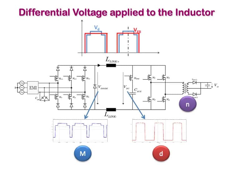
This article is based on newsletter blog written by Dr. Chema Molina, CEO of Frenetic that introduces his innovative approach by integrating a three-phase buck rectifier with a current-fed full bridge.
He discusses role of inductor at buck converters and resonant inductor at LLC. This integration is uniquely characterized by the shared utilization of a singular inductor across both stages, effectively eliminating the need for an additional inductor.
This design can be conceptualized as a dual-stage system where each stage exhibits pulsating voltages interconnected by the inductor.
You can see the diagram of the system in the picture. Importantly, this setup allows for independent control over each stage’s duty cycle, enabling precise manipulation of the inductor’s ripple characteristics.
This aspect is crucial for optimizing performance and efficiency in power conversion applications.
In an effort to explore the dynamics of the system, I focused on manipulating the parameters M (duty cycle of the rectifier), d (duty cycle of the CFFB), and n (turns ratio). This experimentation aimed at achieving a state where the voltage differential (dV) is maintained at zero volts. This intriguing condition raises a fundamental question: Is it feasible to eliminate the inductor from the circuit?
To address this, it is imperative to revisit the foundational principles underlying the use of inductors in electrical circuits. Understanding the core reasons for incorporating inductors will provide critical insights into the implications and feasibility of removing them.
Inductor at Buck Converters
If we take a buck converter as an example, we have two situations.
Switch ON→ We connect the input voltage source with the inductor. The inductor is charged magnetically.
Switch OFF→ The inductor discharges his energy to the load.
Let me consider the theoretical implications of removing the inductor from the circuit. Without an inductor, the current would flow directly from the input voltage to the output, resulting in a condition where the input voltage equals the output voltage. This scenario deviates from the desired operation of a buck converter, where the objective is to reduce (or ‘buck’) the input voltage to a lower output voltage.
The primary function of the inductor in a buck converter is to modulate the input voltage. It does so by temporarily storing energy during part of the switching cycle and then releasing it more smoothly during the remainder of the cycle. This process effectively ‘chops’ the input voltage, allowing for controlled energy transfer and voltage regulation.
Resonant Inductor at LLC
In an LLC converter, the resonant inductor, in conjunction with capacitors, forms a resonant tank circuit. This configuration facilitates efficient energy transfer at specific frequencies, enabling the converter to achieve both step-up and step-down voltage conversion with high efficiency. Understanding the behavior and implications of resonant inductors in such applications is crucial for optimizing converter performance
We can see the main difference between having a DC offset in the current and the impact of the AC ripple in the hysteresis loop and losses.
The LLC resonant inductor has zero average current and its main role is to create a low impedance to the current at a specific current, but, it also stores energy in each cycle. I call these ones, AC inductors.
What is the difference between these two inductors? The magnetizing losses are due to the hysteresis loop.
In the design phase of power converters, a pivotal question arises:
Should the design process for both components be equivalent?
One of the key insights I gained from my thesis supervisor, Jesús Oliver, pertains to the critical analysis of inductors’ energy storage capabilities. The fundamental equation E = Li², where E represents the energy stored, L the inductance, and the current, serves as an essential tool in assessing the maximum energy storage capacity of inductors. However, it’s important to note that inductors in different applications often require significantly different energy storage capabilities.
The complexity in designing inductors primarily lies in calculating core losses, which is especially challenging for AC inductors due to their larger hysteresis loops. This factor makes the analysis of core losses more intricate compared to DC inductors.
In the context of power supplies, the role of the inductor extends beyond mere energy storage. Inductors are crucial for smoothing out currents and, in certain scenarios, play a pivotal role in influencing the current’s frequency through resonance. This dual functionality of inductors – as energy storage devices and as facilitators of smooth, resonant current flow – is integral to the effective design and operation of power conversion systems.
Addressing the initial query: Is it feasible to eliminate the inductor introduced at the beginning of our discussion?
The answer is not straightforward. Theoretically, if both the input and output voltages were consistently identical, there would be no voltage differential, rendering the inductor redundant as it would not store any energy nor influence the current waveform. However, such a scenario is rare and difficult to maintain across various operating conditions. In reality, the equality of voltages occurs only in specific, limited situations. Most of the time, the waveform shared between the input and output is not identical, necessitating the presence of an inductor.
In essence, the primary role of this inductor, similar to that in a buck converter, is to store energy. Given the typical voltage profiles, especially in the rectifier side of circuits, maintaining equal voltages on both sides is impractical. Therefore, in most practical applications and across diverse operating conditions, the inductor remains an indispensable component for managing energy storage and ensuring the desired current waveform.
