Passive Components Blog
No Result
View All Result
  • Home
  • NewsFilter
    • All
    • Aerospace & Defence
    • Antenna
    • Applications
    • Automotive
    • Capacitors
    • Circuit Protection Devices
    • electro-mechanical news
    • Filters
    • Fuses
    • Inductors
    • Industrial
    • Integrated Passives
    • inter-connect news
    • Market & Supply Chain
    • Market Insights
    • Medical
    • Modelling and Simulation
    • New Materials & Supply
    • New Technologies
    • Non-linear Passives
    • Oscillators
    • Passive Sensors News
    • Resistors
    • RF & Microwave
    • Telecommunication
    • Weekly Digest

    October 2025 Interconnect, Passives and Electromechanical Components Market Insights

    Exxelia 4-Terminal Safety Capacitors Compliant with NF F 62-102 Railway Standard

    Wk 43 Electronics Supply Chain Digest

    Samsung Releases Automotive Molded 2220 1kV C0G MLCC

    How to Select Ferrite Bead for Filtering in Buck Boost Converter

    VINATech Offers Smallest 100µF Al-Hybrid Capacitor

    Vishay Unveils SMD 1200V PTC Thermistors in Compact Size

    Power Inductors Future: Minimal Losses and Compact Designs

    Bourns Unveils Automotive 3 Watt Gate Driver Transformer

    Trending Tags

    • Ripple Current
    • RF
    • Leakage Current
    • Tantalum vs Ceramic
    • Snubber
    • Low ESR
    • Feedthrough
    • Derating
    • Dielectric Constant
    • New Products
    • Market Reports
  • VideoFilter
    • All
    • Antenna videos
    • Capacitor videos
    • Circuit Protection Video
    • Filter videos
    • Fuse videos
    • Inductor videos
    • Inter-Connect Video
    • Non-linear passives videos
    • Oscillator videos
    • Passive sensors videos
    • Resistor videos

    How to Select Ferrite Bead for Filtering in Buck Boost Converter

    Power Inductors Future: Minimal Losses and Compact Designs

    Percolation Phenomenon: Degradation of Molded Power Inductors in DC/DC Converters

    Connector PCB Design Challenges

    Efficient Power Converters: Duty Cycle vs Conduction Losses

    Ripple Steering in Coupled Inductors: SEPIC Case

    SEPIC Converter with Coupled and Uncoupled Inductors

    Coupled Inductors in SEPIC versus Flyback Converters

    Non-Linear MLCC Class II Capacitor Measurements Challenges

    Trending Tags

    • Capacitors explained
    • Inductors explained
    • Resistors explained
    • Filters explained
    • Application Video Guidelines
    • EMC
    • New Products
    • Ripple Current
    • Simulation
    • Tantalum vs Ceramic
  • Knowledge Blog
  • Suppliers
    • Who is Who
  • PCNS
    • PCNS 2025
    • PCNS 2023
    • PCNS 2021
    • PCNS 2019
    • PCNS 2017
  • Events
No Result
View All Result
Passive Components Blog
No Result
View All Result

Three-Phase Buck Rectifier with Integrated Current-Fed Full Bridge by Shared Inductors

16.2.2024
Reading Time: 6 mins read
A A

This article is based on newsletter blog written by Dr. Chema Molina, CEO of Frenetic that introduces his innovative approach by integrating a three-phase buck rectifier with a current-fed full bridge.

He discusses role of inductor at buck converters and resonant inductor at LLC. This integration is uniquely characterized by the shared utilization of a singular inductor across both stages, effectively eliminating the need for an additional inductor.

RelatedPosts

Common Mistakes in Flyback Transformer Specs

Accelerating Full Bridge LLC Resonant Converter Design with Frenetic AI

How to design a 60W Flyback Transformer

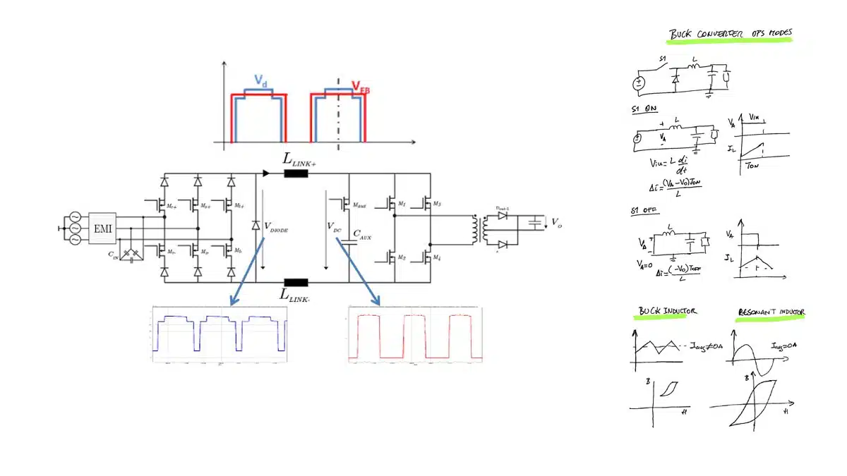
This design can be conceptualized as a dual-stage system where each stage exhibits pulsating voltages interconnected by the inductor.

You can see the diagram of the system in the picture. Importantly, this setup allows for independent control over each stage’s duty cycle, enabling precise manipulation of the inductor’s ripple characteristics.

This aspect is crucial for optimizing performance and efficiency in power conversion applications.

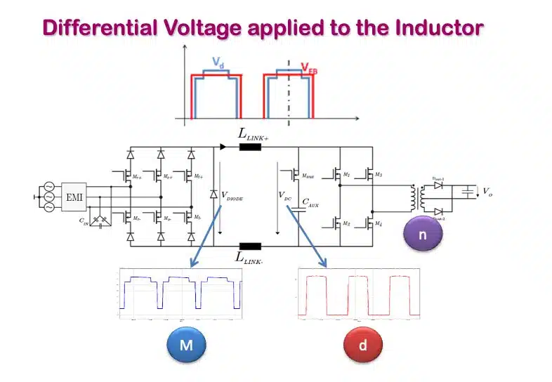
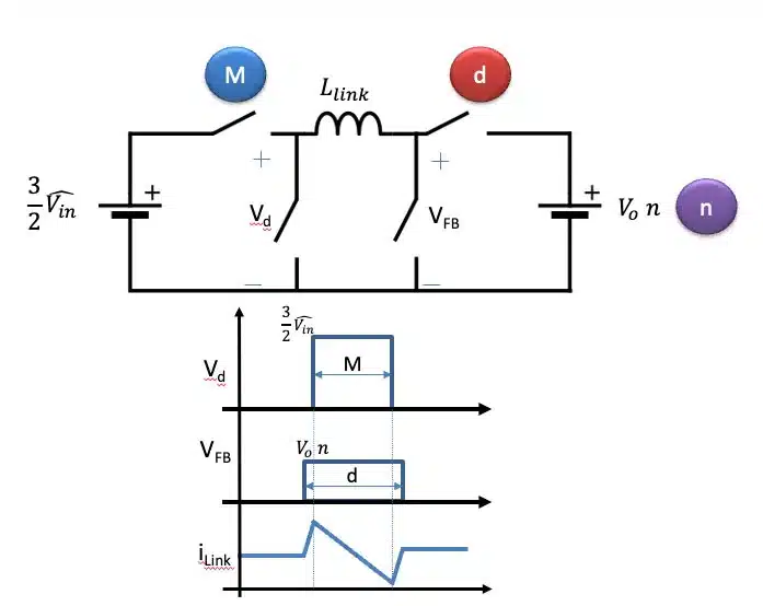
In an effort to explore the dynamics of the system, I focused on manipulating the parameters M (duty cycle of the rectifier), d (duty cycle of the CFFB), and n (turns ratio). This experimentation aimed at achieving a state where the voltage differential (dV) is maintained at zero volts. This intriguing condition raises a fundamental question: Is it feasible to eliminate the inductor from the circuit?

To address this, it is imperative to revisit the foundational principles underlying the use of inductors in electrical circuits. Understanding the core reasons for incorporating inductors will provide critical insights into the implications and feasibility of removing them.

Inductor at Buck Converters

If we take a buck converter as an example, we have two situations.

Switch ON→ We connect the input voltage source with the inductor. The inductor is charged magnetically.

Switch OFF→ The inductor discharges his energy to the load.

Buck Converter OPS Mode

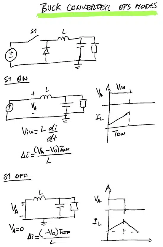
Let me consider the theoretical implications of removing the inductor from the circuit. Without an inductor, the current would flow directly from the input voltage to the output, resulting in a condition where the input voltage equals the output voltage. This scenario deviates from the desired operation of a buck converter, where the objective is to reduce (or ‘buck’) the input voltage to a lower output voltage.

The primary function of the inductor in a buck converter is to modulate the input voltage. It does so by temporarily storing energy during part of the switching cycle and then releasing it more smoothly during the remainder of the cycle. This process effectively ‘chops’ the input voltage, allowing for controlled energy transfer and voltage regulation.

Resonant Inductor at LLC

In an LLC converter, the resonant inductor, in conjunction with capacitors, forms a resonant tank circuit. This configuration facilitates efficient energy transfer at specific frequencies, enabling the converter to achieve both step-up and step-down voltage conversion with high efficiency. Understanding the behavior and implications of resonant inductors in such applications is crucial for optimizing converter performance

We can see the main difference between having a DC offset in the current and the impact of the AC ripple in the hysteresis loop and losses.

Buck inductor vs resonant inductor hysteresis

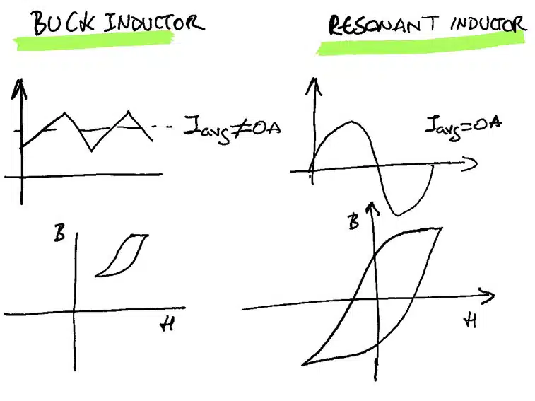
The LLC resonant inductor has zero average current and its main role is to create a low impedance to the current at a specific current, but, it also stores energy in each cycle. I call these ones, AC inductors.

What is the difference between these two inductors? The magnetizing losses are due to the hysteresis loop.

In the design phase of power converters, a pivotal question arises:

Should the design process for both components be equivalent?

One of the key insights I gained from my thesis supervisor, Jesús Oliver, pertains to the critical analysis of inductors’ energy storage capabilities. The fundamental equation E = Li², where E represents the energy stored, L the inductance, and the current, serves as an essential tool in assessing the maximum energy storage capacity of inductors. However, it’s important to note that inductors in different applications often require significantly different energy storage capabilities.

The complexity in designing inductors primarily lies in calculating core losses, which is especially challenging for AC inductors due to their larger hysteresis loops. This factor makes the analysis of core losses more intricate compared to DC inductors.

In the context of power supplies, the role of the inductor extends beyond mere energy storage. Inductors are crucial for smoothing out currents and, in certain scenarios, play a pivotal role in influencing the current’s frequency through resonance. This dual functionality of inductors – as energy storage devices and as facilitators of smooth, resonant current flow – is integral to the effective design and operation of power conversion systems.

Addressing the initial query: Is it feasible to eliminate the inductor introduced at the beginning of our discussion?

The answer is not straightforward. Theoretically, if both the input and output voltages were consistently identical, there would be no voltage differential, rendering the inductor redundant as it would not store any energy nor influence the current waveform. However, such a scenario is rare and difficult to maintain across various operating conditions. In reality, the equality of voltages occurs only in specific, limited situations. Most of the time, the waveform shared between the input and output is not identical, necessitating the presence of an inductor.

In essence, the primary role of this inductor, similar to that in a buck converter, is to store energy. Given the typical voltage profiles, especially in the rectifier side of circuits, maintaining equal voltages on both sides is impractical. Therefore, in most practical applications and across diverse operating conditions, the inductor remains an indispensable component for managing energy storage and ensuring the desired current waveform.

Related

Source: Frenetic

Recent Posts

How to Select Ferrite Bead for Filtering in Buck Boost Converter

23.10.2025
35

Power Inductors Future: Minimal Losses and Compact Designs

22.10.2025
40

Bourns Unveils Automotive 3 Watt Gate Driver Transformer

22.10.2025
8

Percolation Phenomenon: Degradation of Molded Power Inductors in DC/DC Converters

21.10.2025
44

Murata Integrates Component Models into Cadence EDA Tools

21.10.2025
42

Bourns Releases High Inductance Common Mode Choke

16.10.2025
23

High Energy Density Polymer Film Capacitors via Molecular and Interfacial Design

15.10.2025
27

Bourns Releases High Clearance and Creepage 1500VDC Power Transformer

15.10.2025
25

YAGEO Unveils Compact 3.6kW LLC Transformer for OBC EV Charging

13.10.2025
153

Over-Voltage Protection Clippers, Clampers, Snubbers, DC Restorers

13.10.2025
39

Upcoming Events

Oct 30
11:00 - 12:00 CET

Space Ceramic Capacitors with Flexible Testing

Nov 4
10:00 - 11:00 PST

Design and Stability Analysis of GaN Power Amplifiers using Advanced Simulation Tools

Nov 4
November 4 @ 12:00 - November 6 @ 14:15 EST

Wirebond Materials, Processes, Reliability and Testing

View Calendar

Popular Posts

  • Buck Converter Design and Calculation

    0 shares
    Share 0 Tweet 0
  • Boost Converter Design and Calculation

    0 shares
    Share 0 Tweet 0
  • Flyback Converter Design and Calculation

    0 shares
    Share 0 Tweet 0
  • LLC Resonant Converter Design and Calculation

    0 shares
    Share 0 Tweet 0
  • Ripple Current and its Effects on the Performance of Capacitors

    3 shares
    Share 3 Tweet 0
  • SEPIC Converter Design and Calculation

    0 shares
    Share 0 Tweet 0
  • What is a Dielectric Constant and DF of Plastic Materials?

    4 shares
    Share 4 Tweet 0
  • Dual Active Bridge (DAB) Topology

    0 shares
    Share 0 Tweet 0
  • MLCC and Ceramic Capacitors

    0 shares
    Share 0 Tweet 0
  • Flying Capacitors

    0 shares
    Share 0 Tweet 0

Newsletter Subscription


Passive Components Blog

© EPCI - Leading Passive Components Educational and Information Site

  • Home
  • Privacy Policy
  • EPCI Membership & Advertisement
  • About

No Result
View All Result
  • Home
  • Knowledge Blog
  • PCNS

© EPCI - Leading Passive Components Educational and Information Site

This website uses cookies. By continuing to use this website you are giving consent to cookies being used. Visit our Privacy and Cookie Policy.
Go to mobile version