This Frenetic blog article from Pablo Blázques provides introduction to the basic transformer topologies in power converters and its key features.
Usually, in all the transformer topologies, we have an input filter (inductance before the primary side of our transformer), the transformer itself and the output filter. Then, depending on the converter topology, we will have different magnetic components in our design.
Magnetic components
The main functionalities of magnetics in power converters are energy storage, filtering and galvanic isolation voltage/current. These functions are carried out by the inductors and transformers in the power converters.
Inductors
Let’s start with the inductors! Their main functionalities are electrical energy storage, adaptation of the converter input and output sources and phase control of power flow through HF resonant LC stage.
Input filter
Input inductors are wound components that generate a magnetic field to control the current changes. In case of a sudden current increase, an electromotive force is applied against the current in order to control it. While, if the current suddenly decreases, an electromotive force is applied in the same direction as the current.
Output filter
Output filters are used to remove unwanted signals at the output of our analog and digital circuits. Electrical disturbances, both man-made and natural, can affect the performance of our circuit. There are several possible configurations, and the one we chose usually depends on our insertion loss performance.
Transformer
A transformer is defined as a passive component that transfers electrical energy from one circuit to another using electromagnetic induction. The transformer has an influence on the reactive components of the power converter, therefore affecting their performance and size.
Leakage inductance
The leakage inductance is an inductive component that results from the imperfect coupling of the primary and secondary windings. It is represented as an inductance on the primary side, and it is positioned in series with the input inductance.
Magnetic Components in Transformer Topologies
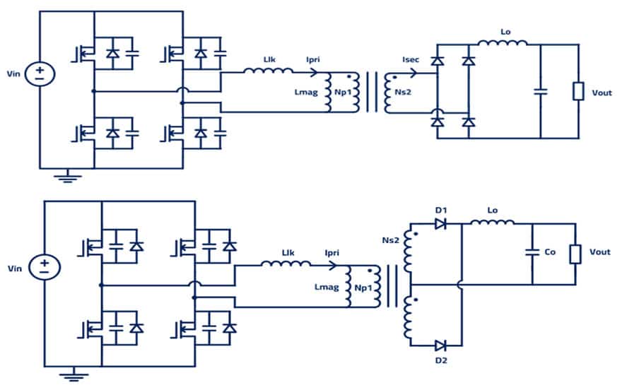
Phase-Shifted Full-Bridge (PSFB): Secondary full wave rectifier and center tap
Phase-shifted full-bridge (PSFP) converter topology is normally used for high-power applications, with the representation of leakage inductance on the primary side. For this kind of design, we can have two different design objectives:
- Aim at the lowest leakage possible to reduce losses in the design
- Aim for a specific leakage inductance to achieve Zero Voltage Switching (ZVS)
LLC Half bridge and Full bridge
As in PSFB, LLC resonant converter will have the same magnetics, but for the resonant tank: used in High power applications and with the leakage inductance representation on the primary side. The LLC topology will have:
Input inductor (with two design options):
- Use it to achieve ZVS
- Try to reduce its value by using the leakage inductance
Output filter
- Controls sudden changes in the output
- Controls the voltage in the output
In LLC we need to design the resonant tank, which includes the external inductor, leakage inductance and magnetizing inductance. All these inductors, with the resonant capacitor, will influence the resonant frequency of our converter. We need to choose them wisely to make our converter work.
Dual Active Bridge DAB
With DAB as a bidirectional isolated DC/DC converter topology, we will be able to achieve bidirectional power transfer. Due to the topology design considerations, we will have an input inductor with the leakage inductance and the magnetizing inductance.
When we switch from one direction to the current inductor that we have on the primary side, will make the current change gradually.
Forward Converter
The forward converter is a DC/DC converter that uses a transformer to increase or decrease the output voltage (depending on the transformer ratio) and provide galvanic isolation for the load.
Used for low-power applications, it has an output filter to control the spikes and sudden changes at the output. Some further considerations for the forward converter:
- The output inductor makes the design not suitable for high-voltage applications compared to the flyback, but a good fit when high output currents are required.
Flyback Converter
The flyback converter is a buck-boost converter with the inductor split to form a transformer, so that the voltage ratios are multiplied with an additional advantage of isolation. Flyback is used for low-power applications, and here the leakage inductance will be represented on the primary side. Further considerations:
- It provides isolation from mains voltages
- Since it doesn’t have an output inductor, as the forward topology does, we will have a high output ripple current. Therefore, Flybacks are more suitable for higher voltage applications instead of higher current.
Summary
All the topologies for transformers and the flyback converters are composed of several magnetics that influence every part of the design. The key to a successful outcome is to design them correctly.
Frenetic Online tool can have a several benefits, such as:
- Fast iteration & design process
- Easy access to results
- Support provided by an engineering team expert in magnetics
- Prototyping
By using Frenetic you can reduce the time to final designs, taking into account all the magnetic components that you can have in your designs.
