
An update on what has been going on at Continental Automotive since we got to know this Phenomenon.

The trend in our technology is always towards higher power density and miniaturization. We know that this brings not only advantages like space and cost savings but can also entail disadvantages – sometimes even unexpected behavior. We at Continental have been faced with a phenomenon on class-II ceramic capacitors which we haven’t recognized so far, I call it “DC-Bias Aging” capacitance loss. Two years ago, at the 2nd PCNS held in Bucharest, “DC-Bias Aging” was brought on stage as a hot topic panel discussion with some MLCC-manufacturers and Continental as user. The aim was to start thinking about how this behavior of a capacitor can be described. This paper will show you what we at Continental and our suppliers of MLCCs have done so far.
The paper was presented by Ladislav Vindiš, Continental Automotive GmbH, Regensburg, Germany at the 3rd PCNS 7-10th September 2021, Milano, Italy as paper No.3.3.
History
Continental has been producing parts for the automotive industry for exactly 150 years. It started with rubber tires and meanwhile we also develop and produce almost all electronic control units that can be found in a modern car. One of these many applications is a radar-based distance control unit which controls actively the distance of the car to its vehicles ahead. During the development of this safety relevant control unit, we noticed a malfunction. And this malfunction brought up this topic on the stage to be discussed and improved.
link to PCNS 2019 MLCC DC BIAS article:
First experience with „DC-Bias Aging“ on MLCCs
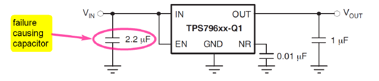
The reason for the malfunction of the control unit was to be found in a voltage regulator which could no longer supply the circuit with the required voltage due to a too low capacitance on its input side. We already knew that when DC-voltage is applied to a class-II-MLCC, its capacitance would be reduced – and we had included that in our worst-case calculations. But it was new for us to find out that the capacity also decreases even further with time – which means, in minutes and hours.

All our MLCC-suppliers have been informed about this – at that time we called it “phenomenon” of class-II ceramic capacitors and we asked them for detailed information and to improve this situation. After intensive research, suppliers and we found out that this phenomenon is described somewhere in the internet but cannot be found in any data sheet of a Multi-Layer Ceramic Capacitor. So, we had to act immediately to avoid further occurrences, to protect all our other projects from such an incident.
How do we manage this “phenomenon” in our company?
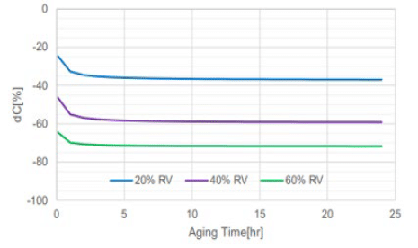
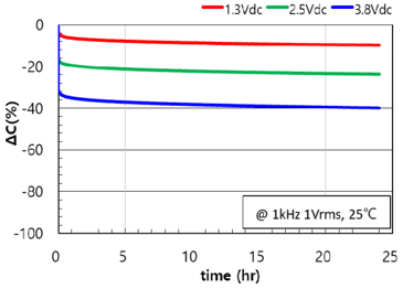
Immediately after we have recognized this kind of behavior, we made several brainstorming together with our suppliers to find out how we can describe DC-Bias Aging characteristic for each single component. We found out that HighCaps are most affected by this phenomenon and we should focus on them first. We decided to request graphs from our suppliers that show the capacitance decrease at 3 different DC-voltages, measured for 24 hours at room temperature. But we refrained from requesting measurements at different temperatures or for a longer duration than 24h as they would be too time-consuming – although we found out that at low temperatures the capacitance loss goes slower. These graphs are now part of our Component Specifications. So, every HW-engineer has access to this information and can use them to estimate the drop in capacitance at a specific DC-voltage.


In addition to our improved component specifications, for each new ceramic capacitor to be introduced, our HW-engineers are actively asked to check whether their schematic is sensitive to a minimum capacitance. If so, the individual conditions for the minimum capacitance value e.g. temperature, DC-Bias voltage or the measurement duration will be part of the component specification. Unfortunately, this minimum capacitance value and the graphs for DC-Bias aging can’t be guaranteed by suppliers. Thus, we always have to add a safety margin. Another way to make many of our HW engineers aware of this additional loss of capacitance in class-II-capacitors is to offer a training. Therefore, we have created a learning video that can be viewed on-demand via our internal eLearning tool that shows the basics of DC-Bias Aging.

How do our suppliers manage “DC-Bias Aging”?
Most of our suppliers offered their support immediately after being confronted with this phenomenon. Some of them already had the foresight to foresee the need to provide such graphs for every single one of their capacitors in their large portfolio. And that’s why they decided to start investigation for a mathematical formula to be able to simulate each combination of voltage, temperature, and duration to calculate the remaining capacitance value. This would have the advantage of being able to provide the remaining capacity for individual conditions in a short time instead of spending time for measurements. It turned out that many (millions) measurements are necessary to be able to offer such a simulation tool. In the meantime, 2 of our suppliers are already using their self-created simulation tool to provide Continental with the requested DC-Bias Aging data. Other suppliers are still investigating or decided not to do such investigations but perform DC-Bias Aging measurements on demand. As E-Learning becomes very popular at this time, more and more suppliers are offering workshops/technical trainings, some even about DC bias aging at MLCCs. This is a good tool to reach and teach people from R&D or quality. And maybe the personal network can be expanded at the same time.
Current challenges and our wishes
One problem is still to get comparable measurement results because either the measurement conditions are not precisely indicated or are left disregarded. For instance, it is important to indicate that the component should be de-aged and then stored for 1 to 3 days before doing measurements. Otherwise, we don’t know how much the aging process has progressed. Therefore, all parameters which do influence the measurement result should be stated there to make the conditions clear.


Another problem are the differences between manufacturers. Of course, components from different manufacturers will show different electrical characteristics. For some well-known parameters we use codes to classify the component, e.g. “K” for the tolerance of ±10% of the nominal capacitance value or “X7R” for the temperature characteristic of ±15% within the temperature range. But what about the characteristic at a certain DC-bias voltage or the DC-bias aging? Unfortunately, there is no standard to make this visible. We detected up to 40% difference in the remaining capacitance at a given DC-voltage between different suppliers. Therefore, every manufacturer should make such data available on its homepage. We as the users of these class-II ceramic capacitors, need and want more information in the datasheets or on the supplier homepage where simulation tools could cover the individual needs.
Conclusion
For our HW-developers it is difficult to find the right capacitor for the individual application because more and more influencing factors have to be considered. Higher frequencies, miniaturization or harsher environmental conditions are some examples. To reduce the risk of choosing the wrong component that could end up causing a car to malfunction or, in the worst case, cost human lives, we add a safety margin to our worst-case calculation, which leads to over-engineering and additional costs. With better and more detailed information about ceramic capacitors e.g. in simulation tools, we should be able to reduce costs and maybe even the time for development. In addition, the data offered by suppliers should be standardized, on the one hand to make them easier to use and, on the other hand, to make them easier to compare between all suppliers. Means, for example, the same precondition for measurements or the same format for the offered data.
References
[1] Datasheet Texas Instruments, www.ti.com

