Earthing (grounding) systems are a fundamental part of low‑voltage electrical installations, directly influencing fault current paths, touch voltages and the speed and reliability of protective device operation. They determine whether an insulation failure results in a quick protective trip or a dangerous shock hazard.
This article explains the IEC 60364 earthing arrangement notation, compares TN‑C, TT, TN‑C‑S, TN‑S and IT systems, and discusses where each is typically applied and what risks or dependencies they introduce.
The central problem addressed is that many engineers work with earthing systems daily without a clear picture of how different arrangements change fault current flow and protection performance. By moving from the least safe to the most robust configurations, the article clarifies how seemingly small differences in conductor arrangements have significant safety and reliability implications.
Key Takeaways
- Earthing systems determine fault current paths and affect safety in low-voltage electrical installations.
- The article explains IEC 60364 earthing arrangements, focusing on TN-C, TT, TN-C-S, TN-S, and IT systems.
- Each earthing type introduces different safety risks and applications, influencing touch voltages and protective device performance.
- TN-S systems are safest, providing separate neutral and PE conductors, while TN-C is the least safe due to reliance on a single PEN conductor.
- Understanding these concepts helps engineers choose the right earthing system for safety and reliability in various applications.
Key points
- IEC earthing letters describe separately the source earthing and the earthing of exposed conductive parts: first letter for source connection to earth, second letter for exposed parts, additional letters C and S for combined or separate neutral and protective conductors.
- T (terra) for the first letter indicates a directly earthed source neutral, while I indicates an isolated or impedance‑earthed source.
- For exposed parts (second letter), T means they are connected to a local earth electrode, whereas N means they are connected to the supply system neutral via a dedicated protective conductor.
- Additional letter C denotes a combined protective earth and neutral conductor (PEN), while S denotes separate neutral and protective earth conductors.
- TN‑C is cost‑effective for distribution but considered one of the least safe arrangements inside installations due to the single PEN conductor; a PEN break can raise all exposed metalwork to phase potential.
- TT systems use a local earth electrode for exposed parts and a earthed source neutral, but fault currents are limited by soil impedance and therefore rely heavily on RCCBs for shock protection.
- TN‑C‑S (PME) combines PEN in the upstream network and separates neutral and PE at the service entry, giving better protection inside the building but still depending on the integrity of the upstream PEN.
- TN‑S provides separate neutral and PE conductors from the transformer throughout the installation, giving the most robust TN‑type safety and electromagnetic performance at the expense of higher cabling cost.
- IT systems use an isolated or impedance‑earthed source with earthed exposed parts; they allow the system to keep running during the first earth fault but require insulation monitoring and are reserved for specialised applications.
- In terms of safety robustness, the sequence is: TN‑C (highest risk), TT, TN‑C‑S, TN‑S (best standard practice), with IT being a special case optimised for continuity rather than general distribution.
Earthing system notation and fundamentals
Each letter of the IEC 60364 classification earthing systems conveys specific information about how the power system and exposed conductive parts are connected to earth.
The first letter describes the source earthing:
- T (terra) stands for a direct connection of the source neutral to earth
- I denotes an isolated source, either completely unearthed or connected to earth via a high impedance.
The second letter describes the earthing of exposed conductive parts, such as the metallic enclosure of a medium‑voltage or low‑voltage switchgear panel. Here, T again means connection to a local earth electrode (local earth pit), whereas N means that exposed parts are connected to the supply system neutral via a protective conductor provided from the source; no independent local electrode is required for protection, although supplementary electrodes may be used for equipotential bonding.
Additional letters C and S refine TN arrangements.
C (combined) indicates that neutral and protective earth are combined into a single conductor called PEN (Protective Earth and Neutral)
S (separate) indicates separate neutral (N) and protective earth (PE) conductors. Combinations such as TN‑C‑S therefore explicitly describe where conductors are combined and where they are separated along the system.
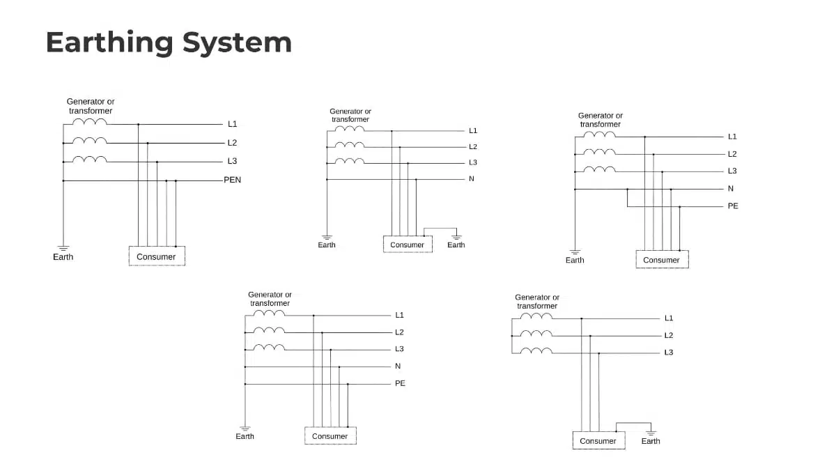
The three main systems used are:
- TN – direct connection of the source neutral to earth, exposed parts are connected to the supply system neutral
- TT – direct connection of the source neutral to earth, exposed conductive parts are connected to a local earth electrode (local earth pit)
- IT – the source is isolated from earth or connected through a high impedance, while exposed conductive parts are earthed, typically via a local or common earth electrode
TN‑C system: combined PEN and its risks
The TN‑C system is presented as one of the least safe configurations, particularly within a building, even though it is sometimes used in distribution networks to save conductor cost. In TN‑C, the source neutral is directly earthed (T as first letter), and exposed parts are connected to the supply system neutral (N as second letter), with an additional C indicating that neutral and protective earth are combined into a single PEN conductor.
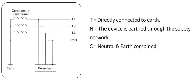
Because all exposed conductive parts are bonded to the PEN, the system’s safety depends critically on the mechanical and electrical integrity of this single conductor. If the PEN breaks upstream—for example due to a loose connection at a pole or near the transformer—the return path for current is lost while phase conductors remain intact. In such a case, equipment metallic enclosures can rise towards phase voltage, creating a touch voltage hazard across the entire downstream installation. The user touching a chassis effectively becomes the return path and closes the circuit, which can lead to serious electric shock.
For this reason, TN‑C is generally not permitted inside buildings and is restricted to certain parts of distribution networks where the utility accepts the risk and applies strict construction and maintenance practices. The main advantage is cost reduction – a single PEN replaces separate N and PE conductors – but this comes with significant safety trade‑offs.
TT system: local earth electrode and RCCB dependence
In a TT system, the source neutral is earthed (first letter T), but the exposed parts of the consumer installation are connected to a local earth electrode (second letter T). Each consumer effectively has their own earth pit, with the protective earth of equipment bonded locally rather than returning via a conductor to the supply neutral.
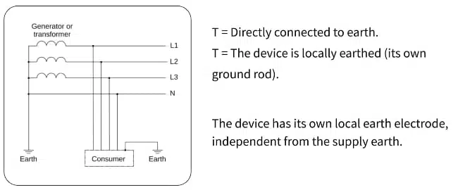
This arrangement is common in rural areas, small houses or farm buildings supplied by a utility that provides only phase and neutral conductors; the consumer is responsible for installing their own earth electrode. The apparent advantage is that there is no shared PEN conductor, and the protective earth path is local; however, fault current characteristics become strongly dependent on the soil resistivity and the quality of the earth electrode.
When a phase conductor faults to an equipment enclosure in a TT system, the return path for the fault current is through the earth electrode, soil and back to the transformer neutral. The loop impedance is typically high, so the resulting fault current may be too low to promptly operate overcurrent devices such as MCBs. This means that, despite the presence of a fault, the MCB may not trip quickly enough to keep touch voltages within safe limits.
Consequently, TT systems rely heavily on residual current circuit breakers (RCCBs) or RCDs for shock protection, using residual current detection (e.g., 30 mA devices) rather than high fault currents to trigger disconnection. If the RCCB is incorrectly selected, bypassed, or fails to operate, or if the earth electrode resistance is poor, the system may become hazardous. Thus, TT is safer than TN‑C in the sense that it avoids combined PEN conductors, but it introduces strong dependence on RCCB functioning and soil conditions.
TN‑C‑S system: PME and practical compromise
The TN‑C‑S system (often called Protective Multiple Earthing, PME) combines TN‑C behaviour in the upstream supply with TN‑S behaviour within the consumer installation. From the transformer to a defined point—typically the service head or entry point to the premises—the supply uses a combined PEN conductor (C). At that point, the PEN is split into separate neutral (N) and protective earth (PE) conductors (S) for the internal wiring.
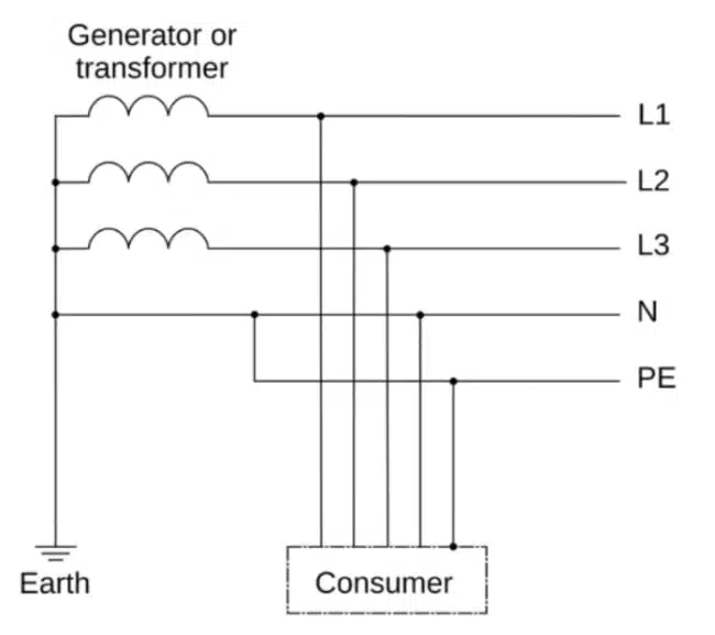
In many urban residential developments, the utility provides a PEN at the property boundary; inside the building, neutral and earth conductors are separated, and all exposed parts are bonded to the dedicated PE conductor. Within the consumer installation, fault currents then return via a low‑impedance metallic path (PE and N back to the transformer), enabling MCBs and other overcurrent devices to operate quickly without relying on soil conduction. This significantly improves protection performance compared to TT under typical conditions.
However, the system still depends on the integrity of the upstream PEN between transformer and service entry. If this PEN breaks before the separation point, dangerous voltages can again appear on bonded metalwork within the premises, similar to a TN‑C failure scenario. Proper design, frequent earthing of the PEN along the route (multiple earthing points), and utility maintenance practices are therefore crucial to mitigate this risk. TN‑C‑S offers a widely used compromise between cost, performance and safety, with good fault clearing characteristics inside installations but non‑zero dependence on the external network.
TN‑S system: fully separate neutral and PE
TN‑S is described as the safest and most robust among the TN systems for critical installations. In TN‑S, the source neutral is earthed (T), exposed parts are connected to the supply system via a dedicated protective earth conductor (N), and neutral and PE remain separate conductors from the transformer secondary all the way to the loads. There is no PEN at any point in the system.
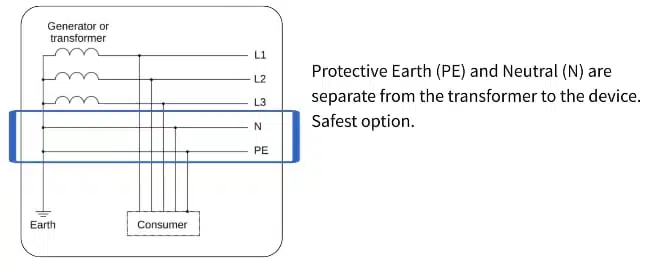
Typical applications include large industrial plants, data centres and hospitals, where high levels of safety, reliability and electromagnetic compatibility are required. From the transformer secondary winding, one conductor is designated neutral, and a completely independent protective earth conductor runs parallel, bonded to all exposed conductive parts and to the source earth.
Because the fault current path uses a dedicated low‑impedance metallic loop (phase–PE–source earth–neutral), protective devices such as MCBs and fuses operate quickly and predictably during earth faults. There is no risk associated with a combined PEN failure, significantly reducing touch voltage hazards in critical environments. Additionally, TN‑S arrangements favour better electromagnetic performance by separating load return currents (neutral) from protective earth conductors, which is beneficial for sensitive control systems and medical equipment. The main drawback is higher installation cost, because every feeder requires an additional PE conductor, sometimes over long distances from the substation to remote loads.
IT system: continuity‑focused special case
The IT system differs fundamentally from TN and TT in that the source is not solidly earthed. Instead, the source is isolated from earth or connected through a high impedance, while exposed conductive parts are earthed, typically via a local or common earth electrode. This arrangement is used in specialised applications such as hospital operating theatres, mines and critical process industries where continuity of supply is paramount.
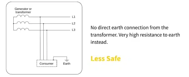
In an IT system, the first insulation fault between one phase and earth does not cause a large fault current, because the source is effectively floating with respect to earth. As a result, the first earth fault does not usually trip overcurrent protective devices or cause immediate supply interruption, which allows critical processes or medical procedures to continue safely while maintenance staff locate the fault.
To maintain safety, IT systems require continuous insulation monitoring; dedicated devices detect the first earth fault and alarm operators so that the fault can be corrected before a second fault occurs. A second earth fault on a different phase can create dangerous fault currents similar to solidly earthed systems, so operating procedures and monitoring are essential. Because of the complexity and specialised protection philosophy, IT is not used for general low‑voltage distribution but is invaluable where uninterrupted power supply outweighs the simplicity of automatic disconnection on the first fault.
Comparative overview of earthing systems
The below table provides benchmarking of the earthing systems from the least safe general‑purpose arrangement to the most robust, and highlights their typical roles. TN‑C is identified as highest risk due to reliance on a single PEN conductor. TT is safer than TN‑C in that it avoids a combined PEN and offers a local earth reference, but safety depends on RCCBs and soil conditions. TN‑C‑S offers a widely adopted compromise for residential and commercial supply, balancing cost and protection by separating PE and N at the service entry while still relying on the upstream PEN. TN‑S is presented as best standard practice for safety and performance in critical or high‑value installations. IT stands apart as best for continuity, used in specialised environments rather than mainstream distribution.
Comparison table of earthing systems
| System | Source earthing (first letter) | Exposed parts earthing (second letter) | Neutral / PE arrangement | Typical applications | Main advantages | Main limitations / risks |
|---|---|---|---|---|---|---|
| TN‑C | T: neutral directly earthed at source | N: exposed parts bonded to supply neutral | Neutral and PE combined as PEN along entire path (C) | Utility distribution segments where regulations allow | Reduced conductor cost; simple topology | PEN break can raise all exposed metalwork to phase potential; generally not permitted inside buildings |
| TT | T: neutral directly earthed at source | T: exposed parts connected to local earth electrode | No PE from source; local earth pit at consumer; phase and neutral supplied | Rural houses, farm buildings and standalone premises | No shared PEN conductor; simple separation between utility and consumer earth | High earth loop impedance; fault current often too low to trip MCBs quickly; heavy dependence on RCCB and soil resistivity |
| TN‑C‑S (PME) | T: neutral directly earthed at source | N: exposed parts bonded to supply PE derived from PEN | Upstream: combined PEN (C); at service entry: PEN split into separate N and PE (S) | Urban residential and commercial installations | Dedicated PE within installation; low impedance metallic fault path; good operation of overcurrent devices | Still dependent on integrity of upstream PEN; a PEN break before separation point can create dangerous touch voltages |
| TN‑S | T: neutral directly earthed at source | N: exposed parts bonded to dedicated PE from source | Neutral and PE separate from transformer to all loads (S throughout) | Industrial plants, data centres, hospitals and critical facilities | No PEN conductor; dedicated low‑impedance PE path; fast and reliable protection; good EMC performance | Higher installation cost due to additional PE conductors over full distance from transformer |
| IT | I: source isolated or impedance‑earthed | T: exposed parts earthed (local/common electrode) | Neutral may be absent or not distributed; PE provided locally; insulation monitoring required | Operating theatres, mines, critical process industries and other continuity‑critical systems | First earth fault does not normally trip supply; high continuity of service; enhanced operational reliability when monitored | Requires insulation monitoring and specialised procedures; second earth fault can be severe; not suited to general distribution |
Practical Issues in Industrial Installations
Beyond the theoretical classification, industrial plants expose some very practical constraints that strongly influence which earthing system works reliably in day‑to‑day operation.
I. Symmetrical TN Systems without Neutral in Industrial Plants
Many industrial plants supply large three‑phase machines and technologies as symmetrical loads in a TN system using three phase conductors and PE only (3L + PE), without distributing the neutral. In this arrangement, all loads are connected line‑to‑line, and the protective conductor is dedicated solely to safety bonding and fault currents, not to carrying any operational current.
This has several advantages in large plants:
- Expensive neutral conductors are omitted on long cable runs, reducing copper cost and cable size.
- Standard overcurrent protective devices (MCBs, MCCBs, fuses) see high and predictable earth‑fault currents via the low‑impedance PE loop, so they disconnect reliably in case of phase‑to‑earth faults.
- Surge protective devices (OVP/SPDs) referenced to PE operate with well‑defined clamping behaviour, because PE is firmly bonded to the transformer neutral in a TN arrangement.
- EMC and mains filters perform as intended: their Y‑capacitors and common‑mode chokes reference a low‑impedance PE, minimising leakage problems and improving noise attenuation.
As a result, TN‑S or TN‑C‑S with three‑phase, no‑neutral feeders are often preferred for heavy machinery and drives in industrial halls, provided that neutral–PE bonding at the transformer and main switchboard is correctly implemented and verified.
II. Why TT Is Unfavourable for Modern Industrial Loads
While TT systems can work well for small residential or rural supplies, they are usually a poor fit for modern industrial installations with many converters, filters and shielded cables.
Two main issues appear in practice:
- Modern machines have relatively large residual currents to PE, arising from EMC filters, surge protection devices, cable shields from frequency inverters and long motor cables. The cumulative leakage often approaches or exceeds the tripping thresholds of standard RCDs, so selective protection with conventional RCCBs becomes impractical or leads to nuisance tripping.
- In TT, the fault and leakage paths run through the grounding electrode and soil. Typical ground resistances in real sites are in the order of a few ohms per electrode, not fractions of an ohm. Single earth rods often measure under about 5 Ω; several electrodes in parallel may reach roughly 1–2 Ω, but these values vary with soil type (rocky, sandy) and seasonal moisture. Higher and unstable ground impedance reduces the effectiveness of EMC filters and SPDs referenced to earth and increases the stress on components, raising the probability of EMC problems and premature failures.
For these reasons, industrial users usually avoid TT where large numbers of frequency converters, filters and shielded cabling are present and instead favour TN‑S‑type solutions with a robust metallic PE back to the transformer.
III. Typical Design and Installation Mistakes
Field experience shows several recurring mistakes that can silently turn a well‑intended TN design into a de‑facto TT system, or prescribe unrealistic earthing parameters.
- Manufacturers of machines or technologies sometimes fail to specify the required earth fault loop impedance (Z_loop) at the power input terminals. In the plant, personnel then simply connect the PE of the machine to the PE terminal of the distribution cabinet without verifying Z_loop by measurement or calculation.
- In the same cabinet, the protective conductor bar may not actually be bonded back to the neutral point of the supplying HV/LV transformer (or to the main earthing bar where that bonding occurs). The result is that exposed parts are effectively referenced only to local earth electrodes, not to the transformer neutral, which unintentionally creates a TT‑like situation instead of the intended TN system.
Another frequent issue is specifying unrealistic ground impedance values for TT designs:
- Designers sometimes call for earth resistances on the order of 0.1 Ω for TT electrodes, which is generally not achievable with practical electrode systems except in very special soil or extensive buried meshes. In most cases, single electrodes give values under about 5 Ω, and even multiple interconnected electrodes in favourable conditions tend to land around 1–2 Ω, with seasonal variation.
- What matters in practice is not just achieving a low value once, but ensuring that the earthing remains within a realistic and safe range over time, across dry–wet seasons and in different soil types (sandy, rocky, high‑resistivity areas).
Clear specification of required Z_loop at equipment terminals, verified bonding between PE bars and transformer neutral, and realistic ground resistance targets consistent with soil conditions are therefore essential practical steps to ensure that the selected earthing system behaves in the way the designer expects.
Conclusion
By understanding the IEC earthing system notation and how different arrangements shape the fault current path, engineers can make informed decisions about safety, protection coordination and system reliability. The differences between TN‑C, TT, TN‑C‑S, TN‑S and IT are not merely academic; they directly influence touch voltages, dependence on devices like RCCBs, and the consequences of conductor failures.
In real industrial environments, these choices are further constrained by practical factors such as symmetrical three‑phase loads without neutral conductors, cumulative leakage currents from EMC filters and drives, realistic soil resistivity, and the quality of PE bonding back to the transformer neutral. TN‑S or TN‑C‑S systems with three‑phase, no‑neutral feeders often provide the most predictable protection and EMC behaviour for large machinery, whereas TT arrangements with significant residual currents and higher, variable ground impedance tend to be unsuitable for modern industrial plants.
Engineers designing or assessing installations should match the earthing system to the application: TT with robust RCCB protection and realistic earth resistance targets for simple rural supplies, TN‑C‑S as a common utility‑supplied compromise, TN‑S for high‑value critical infrastructure and industrial plants, and IT for specialised continuity‑critical environments backed by insulation monitoring. Equally important are clear specification of required earth‑fault loop impedance at equipment terminals, verified bonding between PE bars and the transformer neutral, and achievable ground electrode values that remain stable across seasons and soil conditions so that the selected earthing system behaves as intended over the installation lifetime.
FAQ – Earthing Systems
An earthing system defines how the power system neutral and exposed conductive parts (such as metal enclosures) are connected to earth. It determines the path of fault current, the resulting touch voltages, and how fast protective devices like MCBs and RCCBs will operate during faults.
The IEC 60364 letters describe the earthing arrangement. The first letter shows the source earthing: T (terra) means the source neutral is directly earthed, I means the source is isolated or impedance-earthed. The second letter shows how exposed parts are earthed: T means they are connected to a local earth electrode, N means they are connected via a protective conductor to the supply neutral. Additional letters C and S indicate whether neutral and protective earth are combined (C, PEN conductor) or separate (S, distinct N and PE conductors).
In a TN-C system, neutral and protective earth are combined into a single PEN conductor along the whole path. This saves copper but creates a serious safety risk: if the PEN conductor breaks upstream, all exposed metal parts bonded to it can rise towards phase voltage. A person touching an enclosure may then become the return path for current, so TN-C is usually not permitted inside buildings and is restricted to specific distribution segments.
In a TT system, the source neutral is earthed, but the installation’s exposed conductive parts are connected to a local earth electrode at the consumer premises. Fault current in a phase-to-earth fault flows through the soil back to the transformer neutral. Because the earth loop impedance is usually high, fault current may be too low to trip MCBs quickly, so TT systems rely heavily on RCCBs (RCDs) and good earth electrode resistance to achieve safe disconnection times.
TN-C-S combines a PEN conductor in the upstream network with separate neutral and protective earth inside the installation. From the transformer to the service head, neutral and earth are combined as PEN (C). At the service entry, the PEN is split into separate N and PE (S), and all exposed parts are bonded to the dedicated PE. This gives a low-impedance metallic fault path and good operation of overcurrent devices, but still depends on the integrity of the upstream PEN.
In TN-S, the source neutral is earthed and neutral (N) and protective earth (PE) are separate conductors from the transformer to every load. There is no PEN anywhere in the system. This provides a dedicated low-impedance earth fault path, fast and predictable disconnection, reduced touch voltage risk and better electromagnetic compatibility. The main trade-off is higher installation cost because a PE conductor must be run alongside every feeder.
An IT system uses an isolated or impedance-earthed source while exposed conductive parts are earthed. The first insulation fault to earth produces only a very small fault current, so supply is not usually interrupted. This makes IT suitable for continuity-critical applications such as hospital operating theatres, mines and process plants, but it requires continuous insulation monitoring and proper procedures to deal with a second fault.
For typical low-voltage distribution, TN-S is generally regarded as the most robust and safe of the TN systems because it uses separate neutral and PE conductors throughout and avoids the risks associated with a shared PEN. TN-C-S is a widely used compromise, TT is acceptable with correct RCCB protection and good earthing, while TN-C is considered highest risk and is usually limited to certain parts of distribution networks. IT systems are specialised and optimised for continuity rather than general use.
How to choose and evaluate an earthing system for a low-voltage installation
- Step 1 – Understand the IEC 60364 earthing letters
Start by decoding the IEC earthing notation used in drawings and specifications. The first letter (T or I) tells you how the source neutral is connected to earth, the second letter (T or N) shows how exposed conductive parts are earthed, and any additional letters (C or S) specify whether neutral and protective conductors are combined as PEN or kept separate as N and PE.
- Step 2 – Identify the existing or proposed system type
Review single-line diagrams, utility information and installation plans to determine whether the system is TN-C, TT, TN-C-S, TN-S or IT. Note where any PEN conductor is used, where neutral and earth separate, and whether the installation relies on a local earth electrode instead of a PE from the source.
- Step 3 – Analyse the fault current path
For each earthing option, trace the complete phase-to-earth fault loop. In TN systems, confirm that the loop is a low-impedance metallic path via PE and neutral back to the source. In TT, check that the loop passes through soil and the earth electrode, and in IT, confirm that the source is isolated or impedance-earthed and that the first fault will be limited. This analysis shows how large the fault current can be and how quickly protective devices will operate.
- Step 4 – Check protection devices and disconnection times
Match the earthing system with appropriate protection devices. For TN-S and TN-C-S, verify that MCBs and fuses will trip within required disconnection times based on the calculated earth fault current. For TT systems, confirm that RCCBs (RCDs) are correctly rated and coordinated, because fault currents through earth may be too low for MCBs alone. For IT systems, ensure that insulation monitoring devices are included to detect the first earth fault.
- Step 5 – Evaluate safety, continuity and cost trade-offs
Compare the options against project priorities. TN-C is cheapest in copper but highest risk and generally unsuitable inside buildings. TT avoids PEN conductors but needs reliable RCCBs and good earth resistance. TN-C-S offers a good practical balance for many residential and commercial sites but depends on the upstream PEN. TN-S provides the best all-round safety and EMC performance at higher cabling cost, while IT is reserved for specialised applications where continuity of supply is critical.
- Step 6 – Document the selected system and design controls
Once you select the earthing arrangement, document it clearly in design drawings, specifications and operation manuals. Show conductors (N, PE, PEN), earthing points and electrodes, list the required protective devices (MCBs, RCCBs, insulation monitors) and describe inspection and testing procedures. Clear documentation supports safe installation, commissioning and long-term maintenance.
References
- Gaurav J – TheElectricalGuy, “Earthing Systems Explained: TT, TN‑S, TN‑C, TN‑C‑S & IT (Complete Guide)”, YouTube video, 19 Feb 2026. https://www.youtube.com/watch?v=PYCH4yRwbAk
- Low Voltage Switchgear Course – TheElectricalGuy. https://courses.theelectricalguy.in/low-voltage-switchgear-level1-2
- Earthing System playlist – TheElectricalGuy. https://www.youtube.com/playlist?list=PL_Ht1_dWu2YyfcoIkFnO59uX5QiP-XH2X