
Researchers from German universities in Jena, Ulm and Karlsruhe in co-operation with Skeleton Technologies demonstrated innovative electrode materials carbide-derived carbon (CDC) “Curved Graphene” for high energy density electrical double-layer supercapacitors (EDLCs) with a specific and an aerial capacitance of 114 F g− 1 and 82 F cm− 3.
Utilizing this innovative cell chemistry it is possible to realize an industrial demonstrator exhibiting a nominal capacitance of 5000 F, with a specific energy and energy density of up to 8.4 Wh kg− 1 and 12.2 Wh L− 1 as well as a remarkable lifetime with a capacitance retention of 77% after floating for almost 1400 h at 2.85 V and 65 ◦C.
These results prove that the novel materials considered in this work can indeed be utilized for the realization of commercially available devices with improved cell performance with respect to the state-of-the-art.
Active Material and Electrode
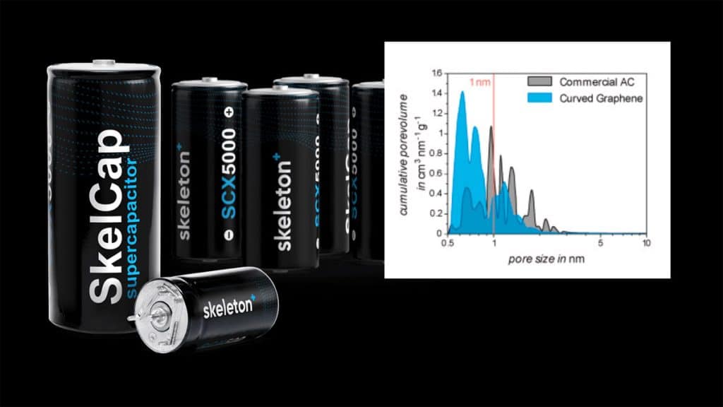
The current state-of-the-art technology for EDLCs uses activated carbon (AC) as the electrode material, in most cases derived from the pyrolysis of coconut shells. Skeleton’s patented “Curved Graphene” Technology represents a significant leap toward an affordable, proven, and scalable increase in energy for high-power energy storage devices while keeping the power in those devices at a similar level as before.
“Curved Graphene” provides the possibility to tailor the ratio of micro-to mesopores to the respective application needs. As the capacitive energy storage process in EDLCs is localized predominantly in micropores (d < 2 nm), a large amount of micropore volume is required. Optimized ACs generally provide a micropore ratio of 0.5–0.6.
Higher values cannot be reached due to the amorphous structure of the respective precursor materials, such as coconut shells, which gives rise to highly disordered carbon structures. The porosity of carbon materials is a result of the interplay of the precursor chemistry and the process parameters in the thermal conversion process of the precursor material to the final carbon material.
Due to the known precursor structure and the high control over the chemistry and process parameters, “Curved Graphene” exhibits a significantly higher purity than ACs derived from organic precursors (Table 1) which in turn leads to fewer side reactions and increases the lifetime of the cell, especially at higher operating voltages and temperatures.
Table 1. Elemental composition of commercial activated carbon and “Curved Graphene”. The given elemental fractions are related to their mass.
| Carbon Type | Carbon | Nitrogen | Hydrogen | Oxygen |
|---|---|---|---|---|
| Activated carbon, commercial | 95% | 0.6% | 0.2% | 4.2% |
| Curved Graphene | 98.5% | 0.5% | 0.2% | 0.8% |
Electrode Preparation and Demonstrator Assembly
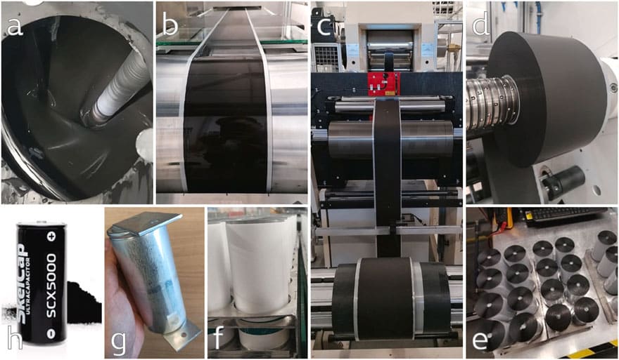
The general demonstrator assembly process is divided into three steps: 1.) electrode production, including slurry mixing, double-side electrode coating, calendering, and slitting; 2.) jelly-roll winding and cell assembly (incl. Electrolyte filling), and 3.) cell testing.
The aqueous slurry was produced according to Skeleton’s proprietary industrial electrode recipe applying “Curved Graphene“ as active material in a planetary mixer (Fig. 1a). Following, the resulting slurry (solid content of 30–35 wt%) was double-side coated on a pilot line (Fig. 1b, line speed below 2 m min−1, 5 m of drying oven) and calendered in Skeleton’s industrial calendar (Fig. 1c) to decrease the resistance in terms of ESR and to increase the electrode density (>20% compression rate), consequently, increasing the overall amount of carbon inside the cell.
After slitting the material to the desired electrode width (125 mm total width) (Fig. 1d), two electrode and separator rolls were joined and wound to an electrode/separator assembly (jelly-roll, Fig. 1e–f). Finally, the current collector tabs were laser welded to the positive and negative terminal (uncoated area), and the resulting jelly-roll-to-tab configuration was transferred into the can. After drying the cell at an elevated temperature of >120 °C under vacuum (<10 mbar) for >12 h, cells were filled under an inert atmosphere with a commercially available electrolyte and, finally, closed with an aluminum pin. The final cell is shown in Fig. 1g and a comparable commercially available application in the same industrial cell format is showcased in Fig. 1f.
Demonstrator Testing
The finally assembled industrial demonstrator consists of “Curved Graphene”-based electrodes, and a high molarity pyrrolidinium-based electrolyte, and was characterized by commonly used electrochemical test procedures for EDLCs, namely constant current, constant voltage or float, constant power, and self-discharge test.
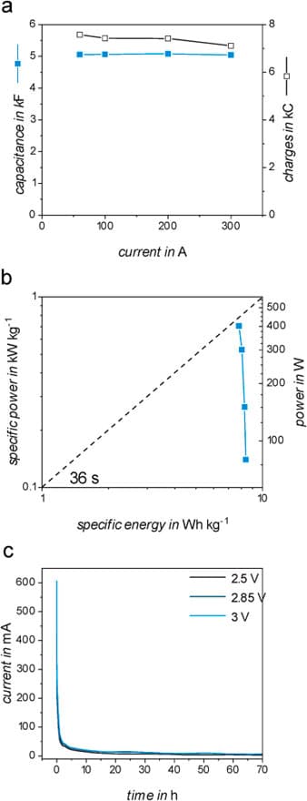
The constant current measurement depicted in Fig. 2a shows the high rate capability of the demonstrator, showcasing the ability to still provide high power with increased energy density. In a current range between 50 and 300 A, the capacitance of the device remains stable around 5000 F. However, the amount of stored charges slightly decreases from 7578 C to 7110 C due to the cell resistance, which causes an increasing ohmic drop with increasing current.
This phenomenon underlines the important role of cell resistance when handling these high currents since it directly reduces the amount of energy that can be stored at increasing current rates. The Ragone plot shown in Fig. 2b highlights the high-power capability of the demonstrator indicating only minor losses in specific energy with increasing power.
Nowadays, supercapacitors are applied in a variety of different applications which are requiring different energy release/uptake. Since EDLCs store charges physically on the electrode surface, the self-discharge of this type of system is naturally relatively high compared to other energy storage technologies. This self-discharge can be characterized by applying a constant voltage to the cell and analyzing the current required to keep the cell at the defined voltage. Fig. 2c shows the current, the so-called leakage current, required to maintain the charged state at different voltages.
It is visible that the self-discharging current decreases fast after reaching the voltage limit which can be attributed to the rearrangement of charges inside the electrical double-layer. After holding the voltage constant for about 3 h, the self-discharge becomes diffusion controlled and the current decreases slightly until reaching a nearly constant value. Additionally, no major differences in the behavior of the leakage current between the different voltage limits can be observed. This highlights the stability of the electrolyte under the test conditions since the decomposition of the cell components by parasitic reactions would consume electrons, and, thus would lead to an increase in the base current.
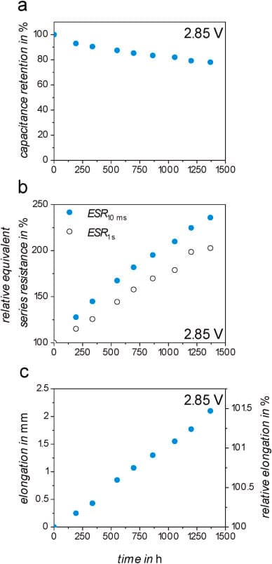
In order to investigate the stability of the materials in an industrial cell format within a comparable industrial environment, a floating test at 65 °C in a time frame of 1500 h with a constant voltage of 2.85 V was performed. The result is shown in Fig. 3.
The demonstrator cell features a capacitance retention of 78% after 1368 h of floating (Fig. 3a). During the complete floating test, the equivalent series resistance (Fig. 3b) increases to 236% when evaluated after 10 ms and by 202% when calculated after 1s. Since floating tests at the maximum operative voltage are extremely demanding for the device, these tests lead to strong cell degradation.
The elongation of the whole EDLC can also be a severe issue for the final application. During 1368 h of the floating test, the cell elongates by 2.1 mm which equals a relative increase of roughly 1.5% (Fig. 3c). This is caused by the evolution of gaseous decomposition products that occur during the aging of the device. Based on the utilized materials, different degradation products can be formed. While the electrolyte can dissolve various decomposition products, the formation of gases in the electrode-electrolyte interphase can lead to pore blocking and an overall increase in the internal pressure of the cell resulting in the elongation of the cell body. Considering the mechanical properties of the cell design, >2 mm of elongation is already the maximum the cell can elongate during aging due to gas evolution. Afterward, the cell classically vents via the safety valve.
The demonstration of “Curved Graphene” as active material in combination with other new materials (binder, electrolyte) in a large standard industrial cylindrical supercapacitor cell format shows promising results in terms of energy, power, and lifetime. These results are the first step for the commercialization of this new class of active material in Skeleton’s supercapacitors.
Considering that the production process was not optimized in terms of slurry recipe, welding steps, and electrode balancing – all highly relevant impactors on cell performance and lifetime behavior – the results are highly promising and showcase the potential for next-generation EDLC technology. Given that “Curved Graphene” was supplied out of industrial pilot reactors, it is reasonable to assume further improvements during the industrialization and scale-up processes, reaching an even higher purity of the material and minimizing side reactions and gas evolution during aging.
Conclusion
Transferring academic research to industrial applications is of high importance in order to solve the problems of our modern society. In this manuscript, we describe the realization of an industrial format EDLC demonstrator based on novel materials and their electrochemical performance evaluation.
The application of “Curved Graphene” instead of standard activated carbons derived from biomass, such as coconut shells, offers superior pore size distribution, as well as a lower content of heteroatoms. Alternative and green binder formulations based on polysaccharides and CMC offer improved film flexibility as well as higher achievable electrode and energy densities than commonly used binders.
The improved electrolyte is based on pyrrolidinium-based salts in ACN which show increased stability compared to the industrial state-of-the-art. The final demonstrator cell displayed a nominal capacitance of 5000 F with a specific energy and energy density of up to 8.4 Wh kg−1 and 12.2 Wh L−1, respectively, as well as a remarkable lifetime with a capacitance retention of 77% after floating for 1400 h at 2.85 V and 65 °C. These impressive cell properties achieved by the combination of novel materials tested in a non-optimized industrial format demonstrator cell show the pathway to increase the performance of EDLCs substantially.
Read the full article in the link below:

