
This article elaborates on properties and selection of storage inductors for DC/DC converter applications. The post is based on Würth Elektronik‘s “DC/DC Converter Handbook” that can be ordered from WE website here. Published under permission from Würth Elektronik.
Key Takeaways
- The article discusses the selection of storage inductors for DC/DC converter applications, emphasizing the importance of rated and saturation currents.
- It highlights that the choice of core material significantly influences inductor behavior, switching frequency, and size.
- Recommendations for ripple current ratios range from 30% to 60%, impacting voltage ripple and heating of capacitors.
- The article also describes the differences between hard and soft saturation in inductors and their implications on performance.
- Ferrite, MnZn, and NiZn are common core materials, each suited for different frequency applications, affecting inductor choice in designs.
A good starting point for a DC/DC converter design is to select the best fit storage inductor and deal intensively with its rated and saturation currents. The core material used in the inductors has a major influence on the saturation behavior, the maximum possible switching frequency, and the component size.
Selection of the Storage Inductors
Different approaches can be found in the literature for calculating storage inductors. Recommendations differ widely, especially in determining the percentage of maximum AC ripple current (ΔI) in relation to the DC rated current. The various sources show values ranging from 0.1x ĪL to 0.9 x ĪL. A low current ripple ΔI means that, other things being equal, the inductance value (L) must be higher, whereas a lower inductance value is sufficient if ΔI is larger.
However, it is often forgotten that the amplitude level of the AC inductor current ΔI has a direct effect on current flow in the input and output capacitors and thus ultimately affects the voltage ripple, as well as heating of the capacitors. Therefore, when dimensioning the storage inductor, it is also important to consider the circuit as a whole. In practice in most applications, a value of current ripple between 30% and 60% in relation to the average inductor current ĪL
has become established.
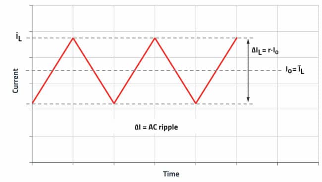
The percentage of ripple current (ripple current ratio) is specified in the formulas below with the ripple current factor r (e.g., 0.35 which corresponds to 35%).
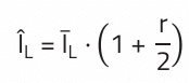
Important: To calculate the peak current ÎL, add half of the ripple current to the average inductor current. The peak inductor current is decisive for selecting the minimum necessary saturation current of a storage choke.
Peak inductor current:
with
ÎL = peak current
ĪL = average inductor current
r = ripple current factor
The storage inductor is often selected based on the datasheets of the switching regulator. In this context, reference design proposals are all too often preferred over computational methods, such as the one presented here. A switching regulator can only develop its full potential with an individually selected storage inductor.
To understand the calculations, let’s take a closer look at the inductor current:
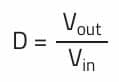
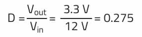
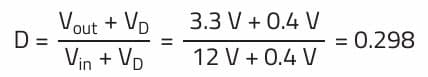
The duty cycle D of the switching event determines the output voltage:
with
D = duty cycle
Vout = output voltage
Vin = input voltage
In the following, we consider a simple step-down converter with a transistor as well as a free wheeling diode, known as an “asynchronous buck converter”.
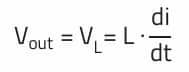
When the transistor in an asynchronous buck converter is turned off, the diode takes over the current flow, causing the inductor to be momentarily at a voltage between the supply and ground. Without inductance, this would be equivalent to a short circuit at the output. This results in a minimum inductance which, together with the output voltage, defines the maximum current rise.
from:
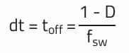
with di = Iout and the switch-off time:
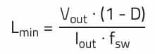
the result is:
The relationships can be derived in the same way for the active phase of the transistor. Here, however, the difference between the output and input voltage is across the storage inductor, which makes the resulting formula more complicated.
The magnitude of the inductance value does not affect the duty cycle (D) with continuous cur rent flow. If a value of at least Lmin is not used in the application, the converter works in discontinuous conduction mode. In this mode there is a poor ratio between the average inductor current and the ripple current, which results in relatively high AC losses. Therefore, this operating mode should be avoided at nominal output current.
example:
For a step-down converter with an input voltage of 12 V to an output voltage of 3.3 V at 1 A with a 500 kHz switching frequency:
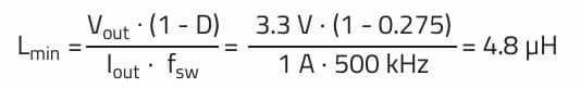
Dimensioning with a 4.8 µH inductor would fully utilize the energy storage capacity of the inductor. In order to compensate temperature drift, inductor tolerance and overload, reserves should be provided for when constructing a circuit in practice. In addition, an inductance value of 4.8µH with its 100% ripple current factor would highly stress the other components in the circuit and worsen the EMC behavior. Therefore, the ripple current factor r (0.3 to 0.6) is added to this formula. Similarly, the voltage drop (VD) of 0.3 V to 0.7 V at the diode should also be taken into consideration. In a synchronous regulator with two transistors this can be omitted, as the voltage drop, due to the low RDS,on, is far below 0.1 V.
For a ΔI = 40% and with a diode forward voltage of VD = 0.4 V, the inductance of the choke is now calculated as follows:
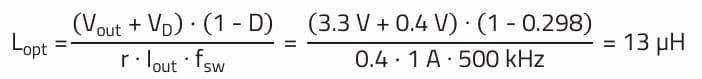
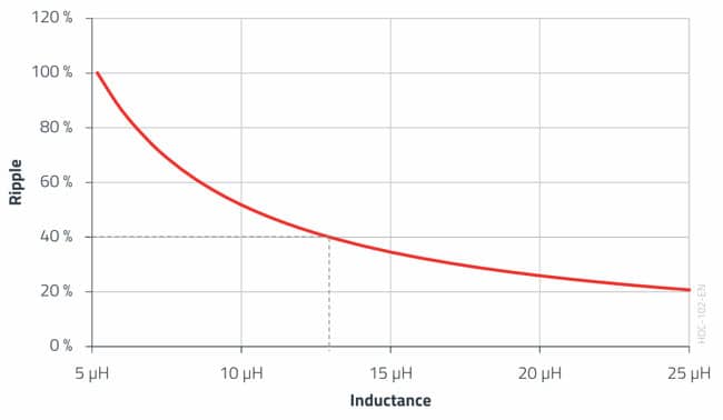
An inductor with a standard value of 15 µH could be used in practice for this design example. As component tolerances and the drop in inductance from the current must be taken into consideration, the choke in this case should not have a minimum tolerance greater than –15% so it does not go below 13 µH; the influence of temperature has not been taken into consideration here. For practical purposes, it must be noted that the ripple current cannot be chosen arbitrarily small. The graph below shows that below ΔI = 20% the inductance value, and thus the inductor size, increases exponentially. Furthermore, it must be observed that the ripple ΔI for a “Current Mode Controlled IC” must have a certain amplitude in order to be able to control in an “agile” manner.
Inductor Rated Current
First, we focused on calculating the necessary inductance value. Now we will look at the rated current that the inductor must withstand.
The average current through the inductor corresponds to the output current of the step-down converter. The RMS current is responsible for heating the inductor, which also generates a power loss with the DC resistance (RDC) of the winding. The RMS current is composed of the average inductor current (DC component) and the ripple current ΔI (AC component). Mainly the maximum DC output current of the converter is of interest for determining the rated current of a storage inductor. Also taking other losses (core losses/AC copper losses) into consideration and depending on the ambient temperature in the application, the average inductor current should always be less than the rated inductor current.
This ‘rated current’ is measured as DC and so only takes the ohmic losses of the wire into consideration. Here it is important to mention that the heating is a quadratic function of the current (from PDC = I2 x RDC). The rated current is only a numerical value in a table and is not intended in any way to precisely design the components. This value can often only be used to compare the series from a particular manufacturer, as competitors differ in their views on the standard copper thickness” on printed circuit boards. In practice, you either allow plenty of tolerance for the temperature increase, or you use the online
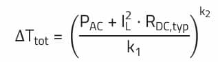
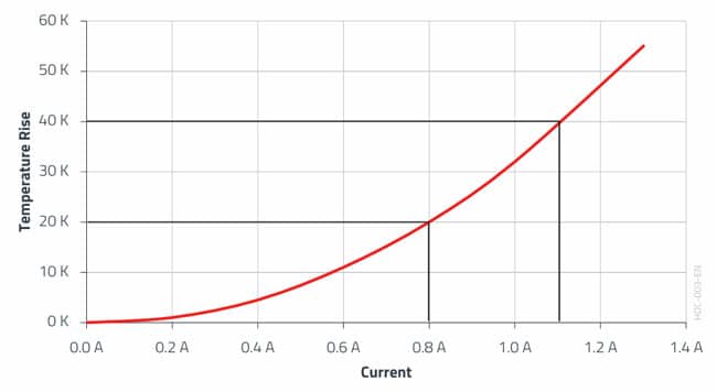
design platform such as Würth Elektronik’s REDEXPERT and simulate the expected heating. Würth Elektronik bases its calculations on a real measurement with a defined test setup. The following equation is used for the temperature extrapolation in REDEXPERT, where two coefficients k1 and k2 are determined
from the heating curve (see Figure 3.) by curve fitting.
The total temperature rise inside the inductor is then:
Inductor Saturation Current
An inductor goes into saturation as the maximum magnetic flux in the core is reached. If this point is exceeded, the storage inductor then resembles an air coil in its electrical behavior and the core material has no influence.
This point is indicated by a drop in inductance. Depending on the core material, the transition is either abrupt or smooth. The terms hard and soft saturation are used. Generally, ferrite cores with discrete air gaps exhibit hard saturation, witnessed by a sharp drop in inductance whereas powder cores with distributed air gaps have soft saturation evidenced by a gradual decrease in inductance.
Both variants have advantages and disadvantages. If hard saturation lies too close to the DC operating point, even a slight increase in the regulator output current can cause a sharp drop in inductance. This leads to a large increase in current, which can damage the semiconductors or force the regulator to shut down (overcurrent protection).
Soft saturation avoids such faults. The inductance of this type drops somewhat earlier, just not abruptly. These inductors react less strongly to short-term load peaks of DC/DC application (e.g., PoL converters).
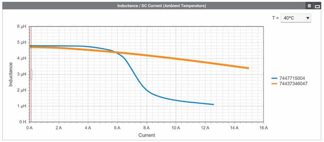
When calculating the ripple current ΔI, care must always be taken to ensure that sufficient distance is maintained from the inductor’s saturation current. This margin is especially important for inductors that exhibit temperature dependent saturation behavior, and this is the case for almost all common inductors with classical ferrite core material.
The saturation behavior of WE inductors can be easily verified with REDEXPERT. The ambient temperature of the application can also be taken into consideration in the simulation and its effect on the saturation behavior of the selected inductor is displayed.
further read: Saturation Current of Inductors and its Measurement
Inductor Core Material
The core material used for the inductors has a major influence on its saturation behavior, the maximum possible switching frequency, and the component size.
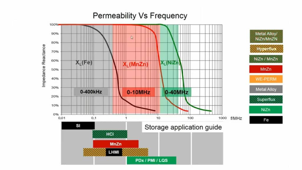
Ferrite is a common core material for storage inductors. The iron oxide determines the underly ing properties, which can be influenced by the addition of manganese oxide and/or nickel oxide as well as zinc oxide. These materials are then typically known as MnZn and NiZn ferrite. They all have in common the capability of being driven up to around 0.5 T, which requires relatively large core cross sections. Furthermore, the component size is also determined by the number of turns. Another material parameter that has an influence is permeability. It is much higher in MnZn than in NiZn ferrite material. This allows relatively high inductance values to be realized compared to inductors with NiZn ferrite with the same number of turns.
NiZn, however, is very well suited for applications in the higher frequency range above approximately 1 MHz, where MnZn losses are greater due to the material’s higher electrical conductivity.
MnZn core material dominates in inductors in low frequency applications up to approximately 500 kHz and NiZn core material is preferred in inductors operating in high frequency applications, but the transitions are fluid.
Modern inductors like the WE-MAPI or the WE-XHMI use carbonyl iron powder (CIP). Due to the structure of the material with a particle size in the single digit µm range, the iron powder with a very wide magnetic drivable range can also be used for very high frequencies. The maximum saturation flux density of over 1 T means the component size can be very much reduced.
FAQ: How to Select Storage Inductors for DC/DC Converters
A storage inductor in a DC/DC converter shapes the inductor current ripple and strongly influences output voltage ripple, capacitor heating, efficiency and EMC behavior.
Designers typically target an inductor ripple current between 30% and 60% of the average inductor current to balance inductor size, losses and capacitor stress.
If the inductance is below the minimum required value, the converter enters discontinuous conduction mode, increasing ripple, AC losses and stressing power components.
The rated current defines how much DC plus AC current the inductor can carry without excessive temperature rise, which depends on winding resistance, core losses and ambient conditions.
Inductor saturation current is the current level where the core reaches its maximum flux, the inductance drops significantly and the inductor starts behaving more like an air core.
Ferrite cores with discrete air gaps normally show hard saturation with a sharp inductance drop, while powder cores exhibit soft saturation with a gradual inductance decrease under rising current.
Core material determines saturation behavior, losses and usable frequency range, so it directly impacts achievable inductance, component volume and converter switching frequency limits.
MnZn ferrites are preferred up to a few hundred kilohertz, NiZn ferrites suit higher MHz ranges, and modern iron powder cores allow compact inductors with high saturation flux and wide frequency capability.
How to select a storage inductor for a DC/DC buck converter
- Step 1: Define converter specifications
Start with input voltage range, desired output voltage, maximum output current and switching frequency specified by the chosen controller or regulator IC.
- Step 2: Choose a target ripple current factor
Select a ripple current factor between 30% and 60% of the average inductor current to balance inductor size, efficiency, capacitor ripple and EMC behavior.
- Step 3: Calculate the minimum inductance
Use the buck converter equations to compute the minimum inductance that keeps the converter in continuous conduction mode at nominal conditions, including diode or switch voltage drops.
- Step 4: Add margin to the inductance value
Increase the calculated inductance to a practical standard value that allows margin for tolerances, temperature drift and overload, and avoids extremely high ripple factors.
- Step 5: Verify inductor rated current
Check that the inductor’s RMS and rated current exceed the maximum load with sufficient thermal margin, taking into account DC resistance, core losses and ambient temperature.
- Step 6: Check saturation current with ripple
Ensure that the peak inductor current, equal to the average current plus half of the ripple, stays safely below the saturation current over the full temperature range.
- Step 7: Select an appropriate core material
Pick MnZn ferrite for lower-frequency designs, NiZn ferrite for high-frequency applications, or iron powder solutions for compact high-flux inductors, depending on loss and size targets.
- Step 8: Validate with simulation and measurement tools
Use vendor tools and thermal simulations to check temperature rise, saturation behavior and losses, and refine the inductor choice before finalizing the PCB design.

