
Thermistors are among the most widely used temperature sensors in electronic systems, yet their strongly nonlinear resistance–temperature characteristic often makes practical implementation less intuitive than simple RTD or IC sensors.
Key Takeaways
- Thermistors are widely used temperature sensors, but their nonlinear characteristics complicate design compared to RTDs.
- NTC thermistors are preferred for precision applications due to their high sensitivity and faster response times.
- Designing a Thermistor-Based Temperature Sensing System involves challenges such as signal conditioning and compensation techniques.
- Using sigma-delta ADCs simplifies design and improves accuracy in thermistor measurement systems.
- For optimal accuracy, leverage ratiometric configurations and select appropriate excitation methods in thermistor applications.
In this article, based on an Analog Devices Analog Dialogue contribution by Jellenie Rodriguez and Mary McCarthy, we look at NTC thermistor-based temperature sensing from a system perspective—starting at the sensor physics and selection, and continuing through excitation, ratiometric configuration, and sigma‑delta ADC interfacing.
The goal is to show how to turn a low‑cost NTC thermistor into a precision temperature measurement channel that is suitable for instrumentation, industrial control, and embedded applications, while also highlighting the key trade‑offs vs. a resistance temperature detector (RTD)-based temperature measurement system and PTC thermistors.
Thermistors vs. RTDs
Resistance Temperature Detector RTD is a type of resistor with resistance that varies as a function of temperature. Thermistors operate in a similar manner to RTDs. Unlike RTDs that only have a positive temperature coefficient, thermistors can either have positive or negative temperature coefficients.
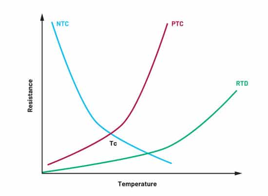
A negative temperature coefficient (NTC) thermistor decreases its resistance as the temperature increases, while a positive temperature coefficient (PTC) thermistor increases its resistance as the temperature increases. Figure 1 shows the response characteristics of typical NTC and PTC thermistors and how they compare to an RTD curve.
In terms of temperature range, the RTD curve is near linear, and the sensor covers a much wider temperature range (commonly –200°C to +850°C) than thermistors due to the thermistor’s nonlinear (exponential) characteristics. RTDs are usually available in a well-known standardized curve while thermistor curves vary depending on the manufacturer. We will discuss this in detail in the Thermistor Selection Guide section of this article.
Thermistors are made up of composite materials, usually ceramic, polymer, or semiconductor (typically metal oxides), which are quite smaller and more inexpensive but not as rugged when compared with RTDs, which are made of a pure metal (platinum, nickel, or copper). Thermistors can detect changes in temperature much faster than RTDs, delivering faster feedback. Thus, thermistors are commonly used sensors in applications that require low cost, small size, faster response rate, higher sensitivity, and with restricted temperature range such as with monitoring electronic equipment, households and building controls, scientific laboratories, or the cold-junction compensation used for thermocouples in commercial or industrial applications.
While Figure 1 compares the basic resistance–temperature curves, it is often helpful to map each sensor type to typical application classes. The table below summarizes common use cases and the main reasons for choosing RTDs, NTCs, or PTC thermistors in those environments.
| Application class | Typical sensor choice | Main reasons for choice |
|---|---|---|
| Industrial process (−200 °C to +600 °C) | RTD | Wide standardized temperature range, good linearity, established IEC curves, stable long‑term drift. |
| Precision lab instruments (−50 °C to +150 °C) | NTC | High sensitivity in limited range, small size, simple 2‑wire connection, lower cost than RTD for moderate temperature span. |
| HVAC, building and white goods (−40 °C to +125 °C) | NTC | Low cost, fast response, many package options (probes, epoxy beads), accuracy sufficient for comfort and appliance control. |
| Power electronics protection, inrush limiting | PTC | Strong resistance increase above switching temperature, inherent current limiting behavior, simple series connection. |
| Harsh high‑temperature environments (up to +300 °C for some types) | RTD or special high‑R NTC | RTDs for standardized behavior and robustness, high‑resistance glass‑coated NTCs where high sensitivity and smaller geometry are needed. |
In many practical designs, thermistors and RTDs are also combined with other sensors (for example thermocouples with NTCs for cold‑junction compensation), so the “best” choice is often dictated by the required temperature range, accuracy budget, and allowed BOM complexity.
In most cases, NTC thermistors rather than PTC thermistors are used in precision temperature measurement applications. There are a few available PTC thermistors that are used in overcurrent input protection circuits or as resettable fuses for safety applications. The resistance-to-temperature curve of a PTC thermistor exhibits a very small NTC region until its switching point (or Curie point) is reached, above which a dramatic increase in resistance of several orders of magnitude occurs within a span of a few degrees Celsius. So, during an overcurrent condition, the PTC thermistor will have a high amount of self-heating beyond the switching temperature and its resistance will increase dramatically, thereby resulting in a reduced current being input to the system and thereby preventing damage to occur.
The switching point for a PTC thermistor is typically between 60°C and 120°C, which is not suitable for monitoring temperature measurements in a wide range application. This article focuses on NTC thermistors that can typically measure or monitor temperature from –80°C to +150°C. NTC thermistors are available with nominal resistances at 25°C, ranging from a few ohms to 10 MΩ. As shown in Figure 1, the resistance changes per degree Celsius is more significant for a thermistor vs. an RTD. The high sensitivity and high resistance values of thermistors make their front-end circuitry much simpler compared to RTDs as a thermistor does not need any special wiring configurations such as 3-wire or 4-wire to compensate for lead resistance. Thermistor design only uses a simple 2-wire configuration.
| Parameters | NTC Thermistors | PTC Thermistors | RTDs |
|---|---|---|---|
| Temperature Range | −80 °C to +300 °C | 60 °C to 120 °C | −200 °C to +850 °C |
| Temperature Coefficient | Negative | Positive | Positive |
| Linearity | Exponential | Exponential | Near linear |
| Sensitivity | High | High | Low |
| Response Time | Fast | Fast | Slow |
| Excitation | Required | Required | Required |
| Self-Heating | Yes | Yes | Yes |
| Wiring Configuration | 2-wire | 2-wire | 2-wire, 3-wire, 4-wire |
| Cost | Inexpensive to moderate | Inexpensive | Moderate to expensive |
| Size | Small | Small | Medium |
Thermistor-Based Temperature Measurement Challenges
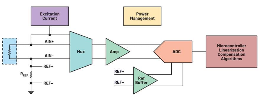
A high precision and accurate thermistor-based temperature measurement requires precise signal conditioning, analog-to-digital conversion, linearization, and compensation, as shown in Figure 2. Though the signal chain looks simple and straightforward, there are several complex factors involved that also impact overall system board size, cost, and performance. There are several integrated solutions available in ADI’s precision ADC portfolio such as the AD7124-4/AD7124-8, which offer multiple benefits when designing a temperature system since most of the building blocks required in the application are built in. However, there are different challenges involved in designing and optimizing a thermistor-based temperature measurement solution.
Challenges include:
- A wide range of thermistors are available in the market.
- How do I select the right one for my application?
- Like RTDs, thermistors are passive devices that do not produce an electrical output on their own. Excitation current or voltage is used to measure the resistance of the sensor by passing a small electrical current through the sensor to generate a voltage.
- How do I select the current/voltage?
- How should the thermistor signal be conditioned?
- How do I adjust the above variables so that the converter or other building blocks are used within their specification?
- Connecting multiple thermistors in a system: How are the sensors connected? Can some blocks be shared among the different sensors? What is the impact to the overall system performance?
- A primary concern about thermistors is their nonlinear response and system accuracy.
- What is the expected error for my design?
- What linearization and compensation techniques are used to achieve the target performance?
This article discusses each of these challenges and provides advice on how to resolve these issues and further ease the journey in designing such a system.
Thermistor Selection Guide
A broad selection of NTC thermistors is available on the market today, so selecting a specific thermistor for your application can be quite challenging. Note that thermistors are listed by their nominal value, which is the nominal resistance at 25°C. So, a 10 kΩ thermistor has a nominal resistance of 10 kΩ at 25°C. Thermistors are available with nominal or base resistance values from a few ohms to 10 MΩ. Thermistors with low nominal resistance (10 kΩ or less nominal resistance) typically support a lower temperature range such as –50°C to +70°C. Thermistors with higher nominal resistance support temperatures up to 300°C.
The thermistor element is made from metal oxides. Thermistors are available in bead, radial, and SMD form. Bead thermistors are epoxy coated or glass encapsulated for extra protection. Epoxy coated bead thermistors, radial, and SMD thermistors are suitable for temperatures up to 150°C. Glass coated bead thermistors are suitable for high temperature measurements. The coating/packaging for all types also prevents against corrosion. Some thermistors will also have additional housing to add further protection in harsh environments. Bead thermistors have a faster response time vs. radial/SMD thermistors. However, they are not as robust. So, the thermistor type to use depends on the end application and the environment in which the thermistor will reside. The long-term stability of a thermistor is dependent on the materials it is made from along with its packaging and construction. For example, an epoxy coated NTC thermistor can change by 0.2°C per year while a hermetically sealed one changes by only 0.02°C per year.
Thermistors have differing accuracy. Standard thermistors typically have an accuracy of 0.5°C to 1.5°C. Thermistors have a tolerance on their nominal resistance value and on their beta value (25°C to 50°C/85°C relationship). Note that the beta value of a thermistor is dependent on the manufacturer. For example, 10 kΩ NTC thermistors from different manufacturers will have different beta values. For higher accuracy systems, thermistors such as the Omega™ 44xxx series can be used. These have an accuracy of 0.1°C or 0.2°C over a temperature range of 0°C to 70°C. So, the temperature range being measured along with the accuracy required over the temperature range determines whether a thermistor is suitable for the application. Note that the more accurate the Omega 44xxx series is, the higher its cost.
Therefore, the thermistor to be used depends on:
- Temperature range being measured
- Accuracy required
- Environment in which the thermistor is used
- Long-term stability
Linearization: Beta vs. Steinhart-Hart Equation
To convert from resistance to degrees Celsius, a beta value is commonly used. The beta value is determined by knowing two temperature points and the corresponding resistance at each temperature point.

Where:
- RT1 = Resistance at Temperature 1
- RT2 = Resistance at Temperature 2
- T1 = Temperature 1 (K) T2 = Temperature 2 (K)
The data sheet for the thermistor normally lists the beta value for two cases:
- The two temperatures being 25°C and 50°C
- The two temperatures being 25°C and 85°C
The user uses the beta value that is closest to the temperature range being used in the design. Most thermistor data sheets list the beta value along with the tolerance of the resistance at 25°C and the tolerance of the beta value.
Higher accuracy thermistors such as the Omega 44xxx series and higher accuracy end solutions use the Steinhart-Hart equation to convert from resistance to degrees Celsius. From Equation 2, three constants—A, B, and C—are needed, and these are provided again by the sensor manufacturer. As the coefficients for the equation are generated using three temperature points, the resulting equation minimizes the error introduced due to linearization (error due to linearization is typically 0.02°C).
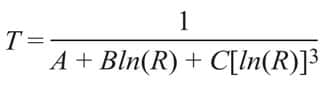
Where:
- A, B, and C are constants derived from three temperature test points.
- R = Thermistor’s resistance in Ω
- T = Temperature in degrees K
Current/Voltage Excitation
Figure 3 shows current excitation of the sensor. An excitation current is applied to the thermistor and the same current is applied to a precision resistor; the precision resistor being used as the reference for the measurement. The reference resistor must have a value greater than or equal to the highest resistance value of the thermistor (dependent on the minimum temperature being measured in the system).
When choosing the magnitude of the excitation current, the maximum resistance of the thermistor must again be considered. This ensures that the voltage generated across the sensor and the reference resistor is always at an acceptable level for the electronics. Excitation current sources require some headroom or output compliance. If the thermistor has a large resistance at the minimum temperature being measured, this leads to a very low excitation current value. Therefore, the voltage generated across the thermistor at hot temperatures is small. To optimize the measurement of these low level signals, a programmable gain stage could be used. However, the gain needs to be programmed dynamically as the signal level from the thermistor changes significantly over temperature.
Another option is to set the gain but use a dynamic excitation current. So, as the signal level from the thermistor changes, the excitation current value is changed dynamically so that the voltage generated across the thermistor is within the electronics’ specified input range. The user must ensure that the voltage generated across the reference resistor is also at an acceptable level for the electronics. Both options require a high level of control, continuously monitoring the voltage across the thermistor to ensure that the signal can be measured by the electronics. Is there a simpler option? Let’s look at voltage excitation – Figure 4.
When the thermistor is excited by a constant voltage, the current through the thermistor will scale automatically as the thermistor resistance changes. Rather than using a reference resistor, a precision sense resistor is now used, its purpose being to calculate the current flowing through the thermistor so that the thermistor resistance can be calculated. With the excitation voltage being used as the ADC reference also, this eliminates the need for a gain stage. There is no workload for the processor in terms of monitoring the voltage across the thermistor, determining whether the signal level can be measured by the electronics, and calculating what the gain/excitation current value needs to be adjusted to. This is the approach used in this article.
Thermistor Resistance Range/Excitation
If the thermistor nominal resistance and resistance range are small, either voltage or current excitation can be used. In this case, the excitation current and gain can be fixed. So, the circuit will be as shown in Figure 3. This method is useful as the current flowing through the sensor and reference resistor can be controlled, which is valuable in low power applications. Also, self-heating of the thermistor is minimized.
Using voltage excitation for a thermistor with low nominal resistance can also be used. However, the user must ensure that the current through the sensor is not too large for the sensor itself or for the application at any time.
When using thermistors with large nominal resistance and large temperature range, voltage excitation leads to an easier implementation. The larger nominal resistance ensures that the nominal current is at a reasonable level. However, the designer needs to ensure that the current is at an acceptable level over the complete temperature range being supported by the application.
A practical way to check that self‑heating remains acceptable is to estimate the temperature rise from the power dissipated in the thermistor. The temperature rise can be approximated as
ΔT≈PDwhere P is the electrical power in the thermistor and D is its dissipation constant in W/°C (typically given in the data sheet as a few mW/°C).
As an example, consider a 10 kΩ NTC with a dissipation constant of 1 mW/°C, biased from 3.3 V in a voltage divider where the thermistor is at 10 kΩ near 25 °C. The current through the device is approximately 3.3 V / (10 kΩ + 10 kΩ) ≈ 0.165 mA, giving a power of about 0.27 mW in the thermistor and a corresponding self‑heating of roughly 0.27 °C. This shows that, for typical bias conditions and dissipation constants, self‑heating can be kept well below 1 °C, but at higher supply voltages or lower resistances the same calculation quickly reveals when the excitation must be reduced.
Importance of Sigma-Delta ADCs in Thermistor-Based Applications
Sigma‑delta ADCs offer multiple benefits when designing thermistor measurement systems. As they oversample the analog input and apply digital filtering, only a simple RC network is usually required at the input, and the designer can trade off noise versus output data rate by selecting the appropriate filter mode. Integrated 24‑bit sigma‑delta converters in this class can achieve more than 20 bits peak‑to‑peak resolution, which is valuable when measuring the relatively small resistance changes corresponding to fine temperature steps.
Other benefits are:
- Wide common-mode range for the analog inputs
- Wide common-mode range for the reference inputs
- Ability to support ratiometric configurations
Some sigma-delta ADCs are highly integrated and include:
- PGA
- Internal reference
- Reference/analog input buffers
- Calibration functions
The use of sigma-delta ADCs simplifies the thermistor design significantly along with reducing the BOM, system cost, board space, and time to market.
Many precision sigma‑delta ADCs also integrate a programmable gain amplifier, precision reference, input and reference buffers, and background calibration functions, which together reduce the number of external components required around the thermistor front end. In the example circuits shown here, devices from the Analog Devices AD7124 family are used to illustrate these concepts, but the same architectural choices—ratiometric configuration, voltage excitation, and integrated PGA/reference—apply broadly to similar precision sigma‑delta converters from other manufacturers..
Thermistor Circuit Configuration—Ratiometric Configuration
Whether you use an excitation current or an excitation voltage, it is recommended to use a ratiometric configuration wherein the reference and sensor voltages are derived from the same excitation source. This means that any variations in the excitation source will not affect the accuracy of the measurement.
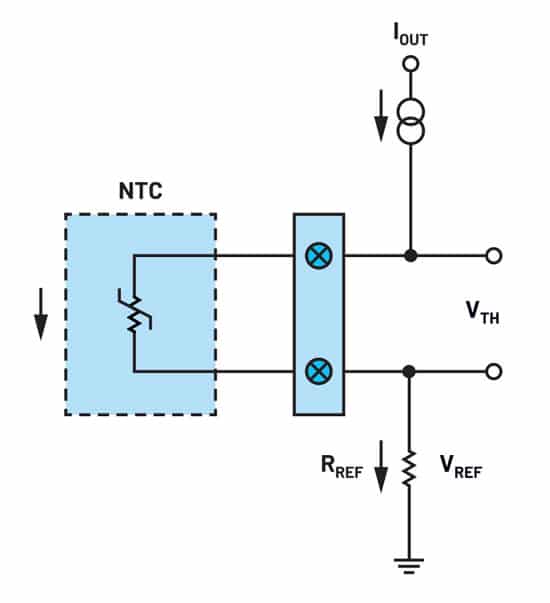
Figure 5 shows a constant excitation current supplying the thermistor and a precision resistor RREF, the voltage generated across RREF being the reference voltage for the thermistor measurement. The excitation current does not need to be accurate and could be less stable since any errors in the excitation current will be cancelled in this configuration. An excitation current is usually preferred over voltage excitation due to its superior control over sensitivity and its better noise immunity when the sensor is in a remote area. This type of biasing technique is commonly used for RTDs or thermistors with low resistance values.
However, for thermistors with higher resistance values and with higher sensitivity, signal levels generated will be larger per change in temperature, so voltage excitation is used. For example, a 10 kΩ thermistor has a resistance of 10 kΩ at 25°C. At −50°C, the NTC thermistor resistance is 441.117 kΩ. The smallest excitation current of 50 µA provided by the AD7124-4/AD7124-8 generates a voltage of 441.117 kΩ × 50 µA = 22 V, which is too high and outside the operating range of most available ADCs used in this application space. Thermistors are also usually connected or located near the electronics, so the noise immunity advantage of an excitation current is not needed.
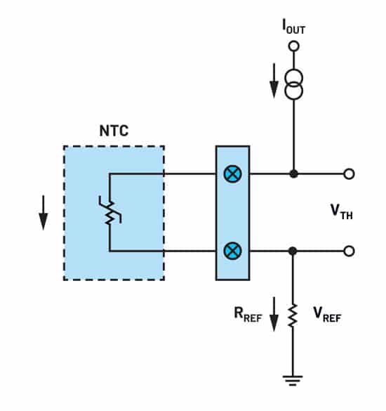
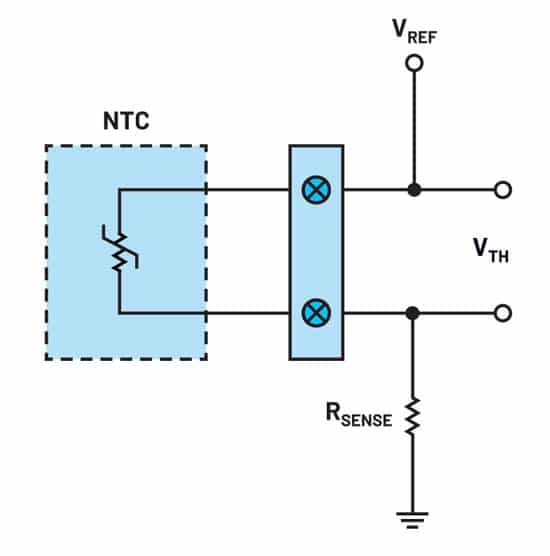
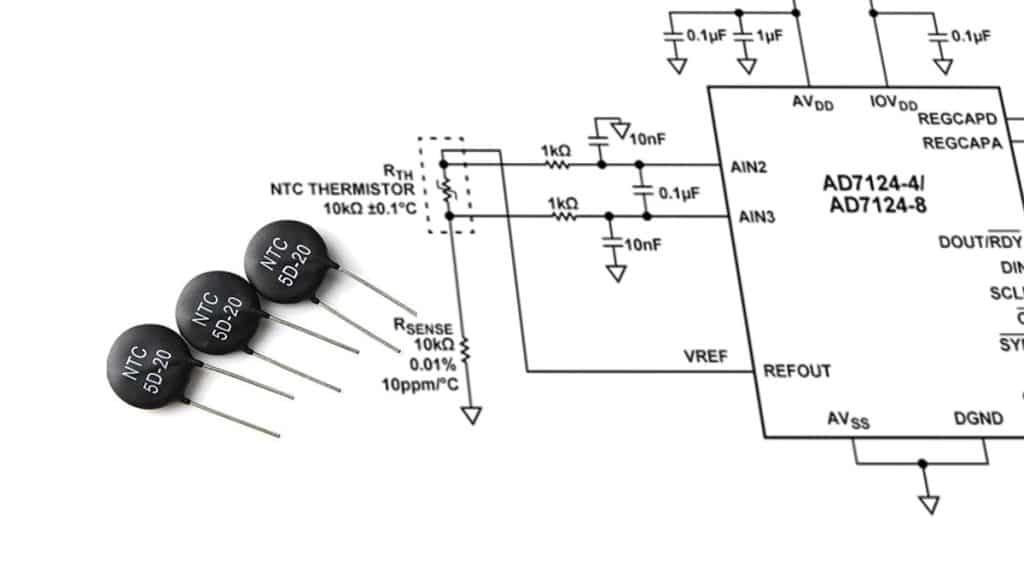
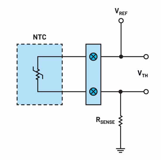
Figure 6 shows a constant excitation voltage used to generate a voltage across the NTC thermistor. Adding a series sense resistor in the form of a voltage divider circuit will limit the current flow across the thermistor at its minimum resistance value. In this configuration, the value of the sense resistor, RSENSE, must be equal to the magnitude of the thermistor’s resistance at the base temperature of 25°C so that the output voltage will be set at the midscale value of the reference voltage when it is at its nominal temperature of 25°C. So again, if a 10 kΩ thermistor that has a resistance of 10 kΩ at 25°C is used, the RSENSE must be equal to 10 kΩ. When the temperature changes, the resistance of the NTC thermistor also changes and the fraction of the excitation voltage across the thermistor also changes, producing an output voltage that is proportional to the NTC thermistor resistance.
If the selected reference voltage that is used to supply the thermistor and/or RSENSE is the same reference as the ADC reference used for the measurement, then the system is configured in a ratiometric measurement (Figure 7) so that any errors associated with the excitation voltage source will be removed.

Note that the sense resistor (voltage excitation) or reference resistor (current excitation) need to have low initial tolerance and low drift as both variables contribute to the overall system accuracy.
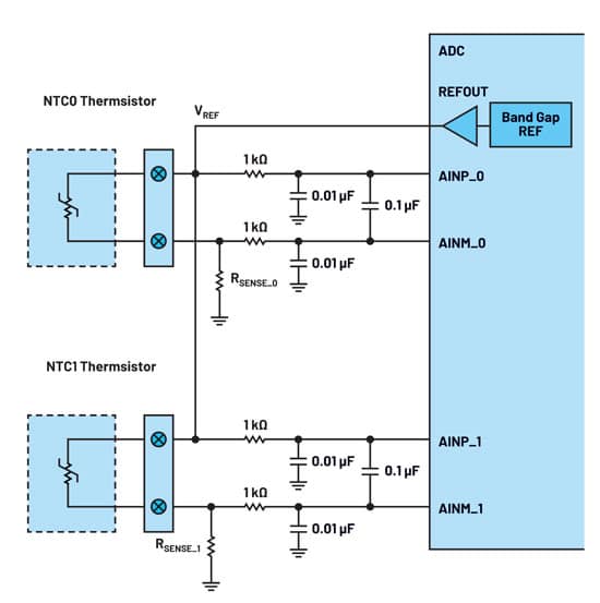
When multiple thermistors are used, a single excitation voltage can be used. However, each thermistor must have its own precision sense resistor as shown in Figure 8. Another option is to use an external mux or switches with low on resistance, which allows sharing of a single precision sense resistor. When using this configuration, each thermistor requires some settling time in the measurement.
For robust systems, it is also useful to consider how thermistor faults will manifest in a ratiometric configuration. An open‑circuit sensor typically drives the ADC input toward the reference voltage (through pull‑ups or leakage paths), while a shorted sensor pulls it close to ground; both conditions are easy to detect in firmware using simple limit checks on the measured code. If a sigma‑delta ADC with integrated diagnostics is used, its input open/short detection modes and self‑test features can further help distinguish between sensor‑side failures, reference resistor faults, and ADC‑side issues.
Summary
In summary, there are multiple concerns when designing thermistor-based temperature systems: sensor selection, sensor connectivity, trade-offs in terms of component selection, ADC configuration, and how these different variables contribute to the overall system accuracy.
Conclusion
NTC thermistors offer an attractive combination of high sensitivity, small size, and low cost for temperature measurement over moderate ranges, provided their nonlinear behavior is handled correctly in the signal chain.
By carefully selecting the thermistor type and nominal resistance, choosing an appropriate excitation method, and using a ratiometric configuration with a precision sigma‑delta ADC, designers can achieve accurate and stable temperature readings without excessive circuit complexity.
When combined with suitable linearization (beta or Steinhart–Hart) and basic fault‑detection strategies, the resulting system can reliably serve applications from HVAC and white goods through to industrial and instrumentation equipment.
FAQ
NTC thermistors offer very high sensitivity over a limited temperature range, small size, and low cost, which makes them attractive for many embedded, HVAC, and appliance applications where moderate accuracy is sufficient. Compared to RTDs, they need simpler wiring and can be easier to integrate into compact systems, while PTC thermistors are more often used for protection and inrush limiting rather than precise temperature measurement.
RTDs are typically preferred when you need a wide standardized temperature range, near‑linear behavior, and excellent long‑term stability, for example in industrial process control or precision laboratory equipment. They are also a good choice when you must cover temperatures well beyond the typical −80 °C to +300 °C range of NTC thermistors or require standardized curves such as Pt100/Pt1000.
The excitation current or voltage determines the power dissipated in the thermistor, which in turn causes self‑heating and can shift the measured temperature away from the true ambient value. Using voltage excitation in a ratiometric configuration with an appropriate series resistor and checking the dissipation against the thermistor’s dissipation constant helps keep self‑heating typically well below 1 °C.
A ratiometric configuration uses the same reference element for both the thermistor divider and the ADC reference, so many error sources such as supply variation and absolute reference drift cancel out. This improves accuracy without adding extra components and is especially effective when combined with a precision sigma‑delta ADC.
A sigma‑delta ADC provides high resolution, flexible digital filtering, and often an integrated PGA and reference, which simplifies the analog front‑end around the thermistor. This combination allows small resistance changes to be resolved as meaningful temperature steps while keeping the external component count low.
How to design a basic NTC thermistor temperature measurement channel
- Step 1 – Define the temperature range and accuracy requirements
Clarify the minimum and maximum operating temperature, required accuracy, and environmental conditions (air, liquid, contact to metal, etc.). This determines whether an NTC thermistor is appropriate or whether you should consider an RTD or other sensor type instead.
- Step 2 – Select a suitable NTC thermistor
Choose the nominal resistance (for example 10 kΩ at 25 °C), beta value, tolerance, and package style based on your range and mechanical constraints. Pay attention to long‑term stability, dissipation constant, and mounting method, as these parameters influence accuracy and self‑heating.
- Step 3 – Choose the excitation method and series resistor
Decide between current and voltage excitation; for high‑resistance NTCs over a wide range, voltage excitation with a series resistor is often the simplest choice. Calculate the series resistor so that the thermistor voltage spans a useful fraction of the ADC input range while keeping dissipation low enough to avoid significant self‑heating.
- Step 4 – Configure a ratiometric measurement with the ADC
Connect the thermistor divider between the ADC reference and ground so that the same reference element sets both the divider current and the ADC reference voltage. This ratiometric arrangement cancels many error sources and allows you to focus on thermistor tolerance and linearization in your error budget.
- Step 5 – Select and configure the sigma‑delta ADC
Use a high‑resolution sigma‑delta ADC with integrated PGA and reference, and set its filter and data rate for the required noise and update‑rate trade‑off. Enable any available calibration and diagnostics functions to improve accuracy and help detect sensor or wiring faults.
- Step 6 – Implement linearization and fault checks in firmware
Convert the measured code to resistance and then to temperature using the beta equation or the Steinhart–Hart model over the chosen temperature range. Add basic fault detection by checking for out‑of‑range codes that indicate open‑circuit or shorted thermistors and logging or reacting accordingly in the system.
Read more about thermistor system optimization and evaluation in the follow up article: Thermistor-Based Temperature Sensing System Optimization and Evaluation

