This blog article from Knowles Precision Devices explains background information on how waveguides and transmission line filters do what they do.
Two important methods for propagating electromagnetic waves around a circuit are waveguides and transmission lines. At a high level, the main difference between these two methods is the number of conductors involved and the types of electromagnetic modes supported. Let’s explore how these types of electromagnetic modes work and how they are supported, or not supported, by waveguides and transmission lines.
Three Types of Electromagnetic Modes
When we say “modes”, what we are referencing is the different solutions to the electromagnetic field equations for the particular structure we are referring to. These three modes include transverse magnetic (TM), transverse electric (TE), and transverse electro-magnetic (TEM).
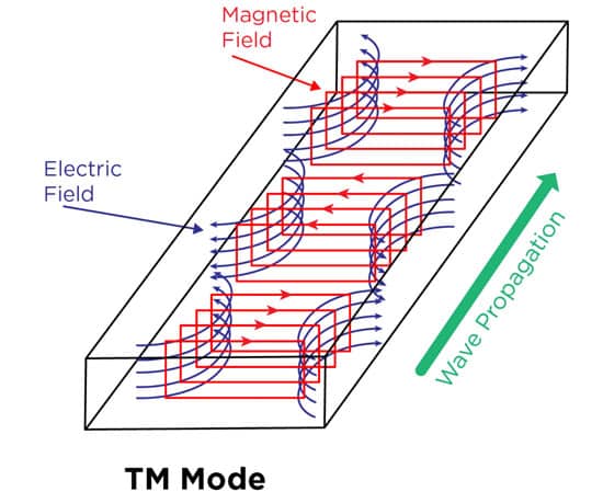
A TM mode solution involves the electric (E) field having components in the z-direction, which is along the direction of propagation, so that the magnetic (H) field is transverse, or at right angles to the z-direction (Figure 1).
On the other hand, TE mode has E field components at right angles to the z-direction as shown in Figure 2.
TEM mode has E field and H field components at right angles to the Z direction. Figure 3a shows an example of an electromagnetic wave propagating through space in TEM mode while Figure 3b shows how TEM mode works in a cross-section of a coax cable.
The Different Modes Supported by Transmission Lines and Waveguides
When we look at transmission lines and waveguides in terms of the electromagnetic modes supported, we can make clear distinctions between the two. A waveguide is a hollow tube made of a single conducting surface, which means it cannot support TEM mode.
We usually see waveguides designed as a metal tube, but in recent years, the development of substrate-integrated waveguide (SIW) technology is changing this. An SIW is basically a rectangular waveguide in which the single conductor walls are formed by plated surfaces and vias. In this format, the wave uses TE mode to propagate in high dielectric-constant materials. A depiction of an SIW is shown in Figure 4.
Since a transmission line is a two-conductor structure, it can carry electromagnetic waves using TEM mode. A common example of a transmission line, although it is sort of going out of style now, is the coax cable shown in Figure 3b, which carries DOCSIS signals to cable TV boxes. Additional transmission line examples, the modes one would usually see, and their traditional performance characteristics compared to what you would see with a waveguide are all outlined in Table 1.
To summarize, the biggest thing to remember when it comes to waveguides versus transmission lines is that a waveguide = one conductor (usually a tube) and a transmission line = more than one conductor, such as the structure seen in a coax cable.
