
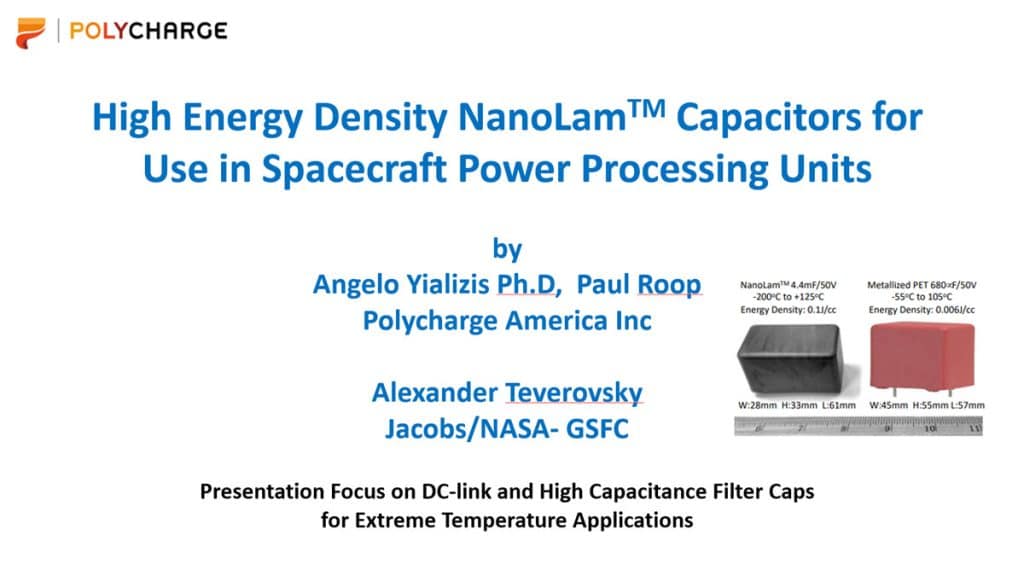

This paper studies NanoLamTM film capacitors’ performance of key dielectric parameters as a function of temperature in the range of -196oC to +200oC to evaluate its capability to meet the space environment operating conditions.
The paper was presented by Angelo Yializis Ph.D, Polycharge America Inc, USA at the 4th PCNS 10-14th September 2023, Sønderborg, Denmark as paper No. 4.1. selected by TPC Technical Program Committee as:
BEST PAPER AWARD
Abstract
Two of the largest and critical components in virtually all Power Processing Units (PPUs) of spacecraft, probes and landers, are energy buffer and DC-link capacitors, used to minimize ripple current, voltage fluctuations and transient suppression. In addition to conventional high temperature requirements, missions to planetary bodies that are distant from the sun, as well as lunar regions that are permanently shadowed, require electrical components with low temperature survivability and predictable and stable functionality at temperatures as low as -240oC.
Current capacitor technologies have severe performance limitations especially when operated at cryogenic temperatures with exposure to cosmic radiation, as well radiation internal to the spacecraft. NanoLam™ capacitors are produced using a nanolaminate composite that is formed using 1-2Mrad of ionizing beta-radiation. The capacitors have excellent stability of dielectric properties over a wide temperature range, superior energy density and specific energy, and resistance to degradation induced by ionizing radiation. I
n this work, electrical measurements of key dielectric parameters are performed as a function of temperature in the range of -196oC to +200oC. NanoLamTM film capacitors are tested both in the form of capacitor elements with voltage ratings of 50V-500V, and packaged capacitors comprising multiple capacitor elements with a capacitance as high as 4.4mF. Results of highly accelerated voltage and temperature stress are presented.
1. Introduction
Cryogenic space applications, such as satellite systems and deep space exploration, require electronic components that can withstand extreme temperatures and harsh environments. Capacitors, being one of the fundamental components in electronic circuits, play a crucial role in these applications. Operating capacitors at cryogenic temperatures presents unique challenges that must be addressed to ensure their reliability and performance. Space missions to planetary bodies that are distant from the sun, as well as lunar regions that are permanently shadowed, require electrical components with low temperature survivability and predictable and stable functionality at temperatures in the range of -240ºC to +125οC. Furthermore, resistance to radiation exposure is a key requirement to reduce the added weight and volume of radiation shielding. The radiation source can be environmental (cosmic radiation) as well radiation that is internal to the spacecraft. For example, Dynamic Radioisotope Power Systems (DRPS), which are a key power generation system in the absence of solar power, require stable and reliable Power Processing Units (PPUs) that can operate in the presence of radiation generated by the power conversion unit.
Energy buffer, DC-link, filter, decoupling and other PPU circuit functions require capacitors that have stable dielectric properties and high reliability for a specific set of operating conditions. This encompasses PPUs for spacecraft, probes, and rovers powered by roll-out photovoltaic arrays tailored to 120V and 300V, and DRPS’s which operate at voltages as low as 50V. PPUs under development for hull ion thruster propulsion systems will be powered by solar arrays with an output of 300V-1000V [1]. Such systems will require higher voltage capacitors, which in combination with high capacitance values, impose further limitations to the available technologies that can service cryogenic temperature applications. The capacitors targeted for this development have a voltage in the range of 50VDC-500VDC, capacitance of 45mF to 4.4mF, and are designed for ripple current frequencies in the range of 10KHz to 100KHz. These ratings are typical of DC-link and energy buffer capacitors used in most PPUs that utilize inverters with silicon carbide and silicon nitride MOSFETs.
2. Performance of Commercially Available Capacitor Technologies at Cryogenic Temperatures
Operation at cryogenic temperatures virtually eliminates the use of electrolytic capacitors for DC applications with high frequency ripple currents. Solid tantalum capacitors, which are used at t liquid nitrogen (LN2) temperature (-196oC) and frequencies above 10KHz undergo both capacitance loss as well as a dramatic increase in dissipation factor and impedance [2]. Multilayer ceramic capacitors (MLCCs) with higher dielectric constant (X7R type), when exposed to LN2 temperatures, undergo a 60% to 80% drop in capacitance, an order of magnitude increase in Equivalent Series Resistance (ESR) and dissipation factor, and also further capacitance instability with voltage bias [3-5]. Low dielectric constant MLCCs ceramic capacitors, such as NPO and COG exhibit a relatively small change in capacitance at low and high temperature; but, they are limited to low capacitance parts.
Ceramic capacitors with specially formulated dielectrics can have a higher capacitance at LN2 temperature than that at room temperature; however, the capacitance drops significantly at higher temperatures and the effect of bias on capacitance is not reported [2]. In general, use of MLCC’s is limited to lower voltage and capacitance values. Larger MLCCs are subject to microcracking, have poor energy density (J/cc), and low specific energy (J/gr). Polymer films are stable at LN2 temperatures; but they are prohibitively large in applications that require tens to hundreds of microfarads. In addition, polymer film capacitors such as polypropylene and polyester cannot withstand high temperatures – the few polymer materials that can be used at high temperature have prohibitively low energy densities. Furthermore, most polymer films are subject to degradation in the presence of radiation [6,7]. Space environments can expose electronic components to high levels of ionizing radiation, which can degrade their performance or cause premature failure. Capacitors for cryogenic space applications need to be radiation-resistant – capable of withstanding the effects of ionizing radiation. Thus, there is a clear need for high energy density and high specific energy capacitors that can operate in the presence of cryogenic temperatures and radiation.
3. NanoLam™ Capacitors for Use in Extreme Temperature Applications
NanoLam™ capacitors, are produced using a solid-state polymer-metal nanolaminate composite, comprising 1000s of high temperature polymer dielectric layers [8,9]. NanoLam™ capacitors exhibit self-healing properties and can handle high continuous and pulsed currents. Moreover, the nanothick polymer dielectric possesses high breakdown strength, resulting in superior energy density. The capacitors are formed using 1-2Mrad of ionizing beta-radiation, and have high resistance to radiation exposure, as well as superior parametric stability with voltage and temperature in the range of -200oC to +200oC.
Compared to conventional polymer dielectric capacitors, the NanoLam™ technology represents a disruptive breakthrough in terms of the dielectric materials used, the manufacturing process, and even the capacitor supply chain. Remarkably, NanoLam™ capacitors are produced in a streamlined one-step process. A large area nanolaminate mother capacitor material with 2000 to 4000 nanothick polymer dielectric layers is produced on a large rotating process drum. A formulated organic monomer and aluminum wire are injected into a machine to produce bulk nanolaminate capacitor material. The large area nanolaminate composite is removed from the process drum and is segmented and processed into individual NanoLamTM capacitor elements (Figure 1). The one-step manufacturing process replaces the film manufacturing process (primarily non-US sources), the metallizing and slitting into bobbins, and the winding operation by the capacitor OEM. The NanoLam™ capacitor manufacturing process allows for complete control of all key capacitor parameters including:
- Polymer Chemistry
- Dielectric constant: Energy storage and Stability of capacitance as a function of temperature
- Self-healing Properties
- Operating Temperature
- Glass Transition Temperature
- Dielectric Thickness (100nm and higher)
- Electrode Design and Metal Thickness

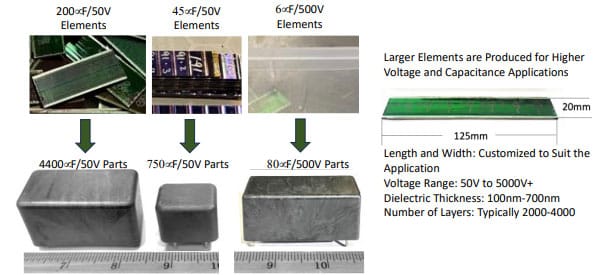
Each capacitor element is fully tested and qualified based on the application requirements. For most capacitor applications multiple capacitor elements are stacked to form larger capacitor blocks, which are lead attached and packaged using conventional packaging methods that include potting in high temperature polymer boxes and over-molding. Taking advantage of the inverse relationship between breakdown strength and dielectric thickness, virtually all NanoLam™ capacitors are engineered with submicron polymer dielectrics [8]. Higher voltage parts utilize internal series sections.
4. Parametric Performance of NanoLam™ Capacitors at LN2 Temperature
Dielectric performance evaluation of NanoLamTM capacitors is performed mainly on capacitor elements as well as on packaged capacitors that comprise element stacks. Figure 2 shows typical capacitance, impedance, ESR and dissipation factor performance as a function of frequency for a 750mF/50V DC-link capacitor developed for a NASA DRPS PPU. The data shows a 10% capacitance drop at -196oC due mostly to reduction in the mobility of the polymer dipoles. The dissipation factor and ESR drop to dramatically lower values at LN2 temperature due to a drop in the resistivity of the metallized aluminum electrodes [10,11]. The drop in capacitance, ESR and DF, is reflected in the impedance characteristic of the capacitor as a function of frequency.

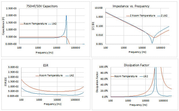
* ESR is higher due to experimental set-up, actual ESR at 4KHz to 40KHz is < 2.0mohm
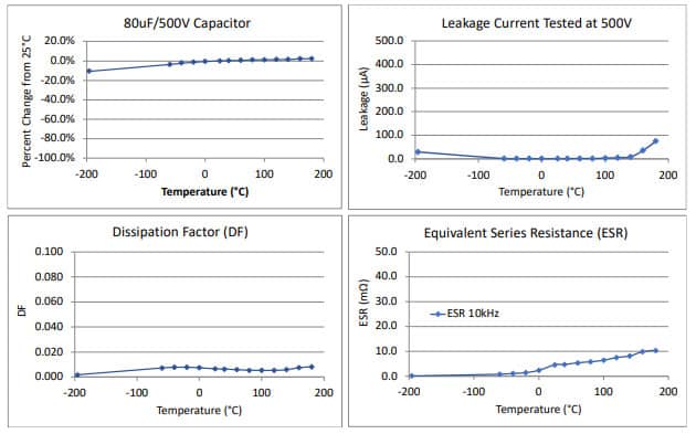
Higher voltage, and physically larger NanoLam™ capacitor elements due to higher dielectric thickness, were also tested in the temperature range of -196oC to +200oC. Typical data shown in Figure 3 demonstrates the variation of capacitance, dissipation factor, ESR and leakage current as a function of temperature. At LN2 temperature the capacitance is predictably reduced by about 10%. At higher temperatures, the capacitance increases by about 2% at 125oC and continues to increase slightly as temperature increases to 200oC. The DF and ESR values also decrease in the same manner as the 50V parts (Figure 2), which are physically smaller with thinner dielectric layers.
The leakage current increases as a function of temperature which is typical of the nanothick NanoLamTM dielectrics. This is due mainly to a Poole-Frenkel electron conduction effect. Electrons, either due to temperature and/or voltage, transition into the conduction band and move along the direction of the applied electric field. In thick polymer dielectrics the majority of these electrons are reabsorbed, which minimizes the effect on leakage current. This phenomenon is common in electrolytic capacitors which also have nanothick dielectrics – although the crystalline lattice of these dielectrics leads to greater leakage currents when compared to the polymer dielectric of NanoLamTM capacitors. The increase in current at LN2 temperature, which drops to normal levels with time on voltage is addressed in Section-6 below.

5. Parametric Stability of NanoLamTM Capacitors Under Extreme Thermal Shock Conditions
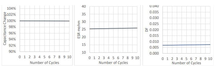
Electronic components in landers or probes may be required to transition rapidly from high-temperature operating conditions to cryogenic temperatures. Such sudden change in operating temperature may not be represented by conventional thermal shock tests. Although microcracking of the nanolaminate structure of the NanoLam™ capacitor is not expected, sudden transition in temperature may affect the capacitor termination, which will be manifested as a change in capacitance, ESR, and dissipation factor. 80mF/500V NanoLamTM capacitor elements were transitioned in seconds from an oven operating at 140oC into an LN2 bath. The parts were maintained at the LN2 temperature for several minutes until their temperature was equilibrated; they were immediately transferred back into the heated oven. This cycle was repeated ten times. The results of this test (Figure 4) do not show any significant change in capacitance, ESR and dissipation factor. The ESR result is particularly important because it can reflect even minor degradation in the capacitor termination.

The coefficient of shrinkage at cryogenic temperature is expected to be lower than the coefficient of thermal expansion (TCE) at high temperature. Since NanoLamTM capacitors can operate for long periods of time at 140oC, a further test was performed where capacitor elements where exposed at a temperature that is higher than the polymer Tg (200oC to 210oC). Above the Tg the TCE of the polymer dielectric increases by at least 2.5X the TCE value below the Tg.
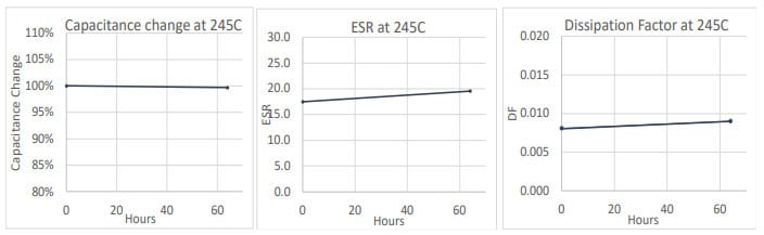
Although the polymer/aluminum nanolaminate has a relatively low TCE when compared to conventional metallized polymer film dielectrics, exposure to a temperature higher than the Tg is expected to exacerbate TCE mismatch effects in the capacitor termination. 38mF/500V capacitor elements were exposed to 245oC for 65hrs in a vacuum environment. Although this is a temperature condition that no conventional metallized polymer film capacitor can survive, the test results in Figure 5 show only a relatively minor degradation in capacitance, ESR and dissipation factor.

6. Self-healing Performance Under Highly Accelerated Tests of Voltage and Temperature
Effect of the Polymer Dielectric: The ability of any metallized capacitor to self-heal at a given electrode and dielectric thickness, is primarily a function of the O:C and H:C ratios in the chemical structure of the polymer dielectric. Carbon and aluminum are removed from the breakdown site by conversion of aluminum to Al2O3 – and carbon to CO, CO2, CH3, CH4, and other low molecular weight hydrocarbons. Unlike wound metallized capacitors, the solid-state NanolamTM capacitor composite does not rely on the air gap between the windings to supply the required amount of oxygen to aid the self-healing process. Instead, the monomer is formulated to maximize the O:C and H:C ratios. Wound capacitors, either when the polymer chemistry has no oxygen (e.g. PP) or when the H:C and O:C ratios are low (e.g., PET, PPS and PEN), have to take into consideration the loss of the air gap when exposed to a space environment for extended periods of time.
Effect of Temperature: The high temperature performance of the NanoLamTM capacitors is a result of the high glass transition temperature of the polymer dielectric (Tg>200oC). Unlike higher temperature thermoplastic capacitor films such as PET, PPs and PEN which rely on the thermal stability of aromatic polyunsaturated benzene ring chemistry to increase the softening and melting point of the polymer, the NanolamTM polymer is cross linked using beta-radiation and has no melting point. The NanolamTM polymer chemistry is fully saturated which leads to higher O:C and H:C ratios that maximize the self-healing process for a given electrode resistivity/thickness.
Effect of Metal Electrodes: The above discussion assumes that the metalized electrodes, which are typically aluminum for most DC applications, have a fixed resistivity (ohm/sq). The resistivity/thickness of the aluminum electrodes in combination with electrode segmentation (used in different capacitor designs), has the greatest impact on the self-healing properties of a metallized capacitor. The energy dumped in a single self-healing event has been found to be inversely proportional to the electrode resistivity [12]. As the energy of a single breakdown increases, so does the probability of a breakdown in adjacent capacitor layers. A large number of consecutive self-healing events will lead to high capacitance loss. In conventional thermoplastic metallized film capacitors continuous self-healing activity can cause a thermal runaway condition where the capacitor will thermally deform or melt-down before it becomes an open circuit.
Initiation of Breakdown/Self-healing Events as a Function of Temperature: The voltage level at which self-healing events are initiated is important because sustained application of voltage will continue to generate breakdowns causing capacitance loss. Figure 6, shows the voltage level at which self-healing events are initiated in NanoLamTM capacitors at different temperatures.

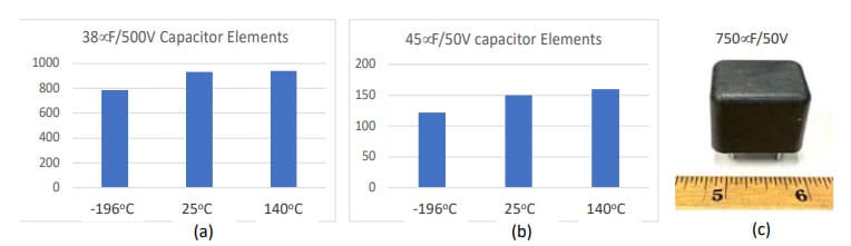
Two significant observations can be made based on the data in Figures 6(a) and (b). The initial breakdown of the two different types of capacitor elements, which have different dielectric thickness, is virtually the same at 25oC and 140oC. This does not come as a surprise because the Tg of the NanoLamTM dielectric is >200oC and the polymer is not expected to lose any significant amount of mechanical and dielectric strength below this temperature. This is a key differentiating factor between NanoLamTM capacitors and most metallized capacitor films that have a Tg in the range of -20oC(PP) to 120oC(PEN), which lose mechanical and dielectric strength as the temperature exceeds the softening point of the polymer.
Figure 6, also shows that the initial breakdown of the capacitors drops at the LN2 temperature. This drop is attributed to the change in the electrode resistivity. Bulk aluminum with a purity of 99.99%, which is used to form the capacitor electrodes, drops in resistivity by more than an order of magnitude between 25oC and the LN2 temperature [10,11]. The metallized electrodes are expected to have more defects and impurities than bulk aluminum; however, the resistivity as measured by the ESR (Figures 2 and 3) drops enough to impact the self-healing properties of the capacitor. Despite the negligible drop in voltage at which breakdown events commence, relative to the capacitor’s rated voltage, it’s possible to compensate for this. Based on the specific application and ESR requirements, one could design the capacitor with electrodes that have higher resistance per unit area (ohm/sq).
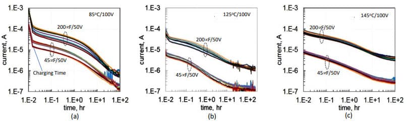
Leakage Current During Highly Accelerated Stress Tests: Capacitor elements designed for 50V DC-link and energy buffer applications, when tested for leakage current over 100hrs at 85oC and 100V ( 2xVrated), undergo a drop in leakage current by two orders of magnitude (Figure 7a). At higher temperatures, currents after 100 hours of testing decrease about an order of magnitude (Figures 7a and 7b). The difference in leakage current between the two types of capacitor elements, which have the same dielectric thickness, is attributed to their capacitance values.

The capacitor elements shown in Figure 7 were placed on a Highly Accelerated Life Test (HALT) at 145oC/100V and measured periodically over a period of 1000hrs – Figure 8(a). Furthermore, virgin capacitor elements measured initially at 20oC/100V were periodically remeasured after HALT tests at various conditions of temperature, voltage and time. Figure 8(b) shows that a few parts that had some initial damage, mainly from handling, self-healed and the leakage current recovered after some time at temperature and voltage.

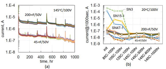
Figure 9, shows a similar reduction of leakage currents in 200mF/50V capacitor elements tested at 20oC for short periods of time at highly accelerated voltage stress, and at lower voltages over a longer test period.


At 150V (Figure 9a) the 50V parts are expected to undergo some self-healing events immediately upon the application of voltage. The test results show that the solid state NanoLamTM capacitors self-heal effectively after initial and subsequent clearing events. The self-healing events cause a high initial current which drops as the carbon tracks generated by the breakdown activity either blow out in a fuse-like fashion, or oxidize. As the application of voltage continues, additional breakdowns of less severity occur that cause a transient increase in current.
7. Resistance to Radiation Exposure
As noted above, the NanoLamTM capacitor dielectric is highly cross linked using 1-2Mrad of beta radiation. As a result, the capacitor dielectric is highly resistant to degradation in the presence of radiation. NanoLamTM capacitors with the same polymer dielectric and overall construction have been tested while operating in the presence of radiation, using the Saturn and HERMES III Sandia accelerators. These capacitors were qualified for use in an application where they will be permanently exposed to radiation levels that are harmful to commercially available polymer film capacitors.
8. Energy Density of NanoLam™ Capacitors


Comparing the energy density of NanoLam™ capacitors to other technologies presents a challenge. Few capacitors possess the unique combination of stable dielectric properties across a wide temperature range, high capacitance, high voltage, self-healing attributes, and resistance to radiation damage, making NanoLam™ capacitors distinct. The 4.4mF/50V NanoLamTM energy buffer capacitors which comprise multiple 200mF/50V elements tested above, are compared in Figure 10, to state-of-the-art low voltage metallized polymer film capacitors.
Conventional low voltage high microfarad metallized film capacitors for DC applications, are produced using an ultrathin polyester film that has the same dielectric constant as the NanoLamTM polymer dielectric used in this application (k=3.2). The polyester film at a thickness of 1.2µm is limited to a temperature of 105oC and has an intrinsic breakdown strength <400V/µm. The NanoLamTM capacitor has a dielectric thickness of 300nm and an intrinsic breakdown strength of 1000V/µm. As a result, the NanoLamTM capacitor has 16X higher energy density, not including the weight and volume of a protective radiation shield that maybe necessary if the metallized film capacitor is used in the presence of radiation.
9. Conclusions
Selecting capacitors for cryogenic space applications requires careful consideration of their temperature range, dielectric properties, mechanical stability, leakage current, and radiation resistance.
The results of this investigation demonstrate that the solid-state NanoLamTM capacitors have a polymer dielectric that has stable capacitance and dissipation factor in the temperature range of -196oC to 200oC.
The NanoLam™ capacitor can withstand a limited number of severe thermal shock cycles from -196oC to +140oC with no significant degradation of key electrical parameters.
The capacitors can withstand exposure to temperatures as high as 245oC for tens of hours with minimal parametric degradation. Breakdown tests in a temperature range from -196oC to 140oC, in combination with temperature and voltage HALT testing, demonstrate that the solid-state NanoLamTM capacitors have excellent dielectric strength and self-healing properties without the need for an air gap to supply oxygen.
NanoLamTM capacitors as demonstrated above and in previous work [8,9], have superior energy density when used in DC-link and filter applications that require large capacitance and voltage in the range of 50V-1000V.
10. Acknowledgment
The authors want to acknowledge Dr. Christopher B. Barth of NASA GRC-LETO for his valuable collaboration as well as overseeing much of this development.
11. References
- D. M. Goegl and O. Filimonova, “High Voltage Solar Array Development for Space and Thruster-Plume Plasma Environments”, IEE, Transactions on Plasma Science, Vol 50, March 2022
- A. Hammoudand, S. Gerber, R. L. Patterson and T. L. MacDonald, “Performance of Surface-Mount Ceramic and Solid Tantalum Capacitors for Cryogenic Applications”, Electrical Insulation and Dielectric Phenomena, IEEE Atlanta, Georgia, October 25-28,1998
- F. Teyssandier and D. Prele, “Commercially Available Capacitors at Cryogenic Temperatures”, Ninth International Workshop on Low Temperature Electronics – WOLTE9, Jun 2010, Guaruja, Brazil.
- A. Teverovsky, “Reliability of Electronics at Cryogenic Temperatures an Approach to Reliability Testing of High-Voltage Drivers at Cryogenic Temperatures”, NASA Electronic Parts and Packaging Program (NEPP), QSS Group, Inc. Code 562, NASA GSFC,
- Ming-Jen Pan, “Performance of Capacitors Under DC Bias at Liquid nitrogen Temperature” US Naval Research Laboratory, Multifunctional Materials Branch, Code 6350, published by Elsevier, Cryogenics, 03, 2005
- J.R. Laghari, “High-voltage pulsed life of multi-stressed polypropylene capacitor dielectric” IEEE Transactions on Nuclear Science, Institute of Electrical and Electronics Engineers, Journal Volume: 39, 1992
- M.Ferry, Y. Ngono-Ravache, C. Aymes-Chodur, et.al, “Ionizing Radiation Effects in Polymers” Reference Module in Materials Science and Materials Engineering, 2016
- A. Yializis, A Disruptive DC-Link Capacitor Technology for Use in Electric Drive Inverters, European Passive Components Institute 10-13th September 2019, Bucharest, Romania
- A. Yializis. “High Energy Density Solid State Polymer Capacitors for Space Applications”, 4th Space Passive Components Days, International Symposium 11-14 October 2022 | ESA\ESTEC, Noordwijk, Netherlands
- K. F. Pawlek and D, Rogla, “The Electrical Resistivity of Silver, Copper, Aluminum and Zinc as a Function of Purity in the Range of 4oK to 298oK”, Cryogenics 1966.
- J. Polinski, Matrials in Cryogenics. European Course in Cryogenics, CERN Geneva, August 2010
- DG. Shaw, SW. Cichanowski, GR. Newcomb, A. Yializis, Electrical properties and aging mechanisms in metallized polypropylene film capacitors, 1982 IEEE International Conference on Electrical Insulation, 27-34. 1982

