
This article based on Frenetic newsletter is exploring role of High-frequency Magnetics in Formule 1 Power Electronics.
In today’s fast-paced world of racing, advanced technology and innovative design are fundamental in gaining a competitive edge, and Power Electronics definitely play a crucial role in the performance of F1 cars.
Power Electronics is a rapidly evolving field that deals with the conversion, control, and management of electrical power.
Power Electronics and High-frequency Magnetics are crucial for F1 car performance:
- Contributing to a faster, more efficient, and precise control over the car.
- Providing a better energy storage, control over electric motors, and power conversion systems.
- Advancements in technology are expected to drive continued innovation and growth.
- The competitiveness and excitement of F1 racing are expected to be further enhanced by these advancements.
High-frequency Magnetics in F1
High-frequency Magnetics are a key component, used to control and convert electrical energy at high frequencies, typically between 10 kHz and several hundred kHz. In the high-speed world of F1 racing, Magnetics are used in a variety of applications, including energy storage, electric motors, and power conversion systems.
One of the primary usages of HF Magnetics in F1 racing is in the energy storage systems. F1 cars are equipped with Energy Recovery Systems (ERS) that capture and store the energy generated during braking and use it to boost acceleration with the MGU-K.
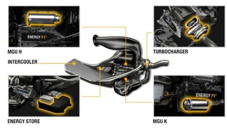
These systems rely on Magnetics in their power conversion and storage systems to efficiently convert and store energy. You can see all these components in Figure 1.
The most common type of energy storage system in F1 racing is the battery, which stores electrical energy in a chemical form. Magnetics are used in the battery management systems to regulate the charging and discharging of the battery, ensuring optimal performance and safety.
Another application of High-frequency Magnetics in F1 is in the electric motors. F1 cars use electric motors in their hybrid powertrains, which work in tandem with the internal combustion engine to improve performance and efficiency. Magnetics are used in the motor control systems to convert the electrical energy from the battery into the appropriate voltage and frequency for the motor.
In addition to their use in energy storage, electric motors, and power conversion systems, HF Magnetics are also employed in other applications in the F1 world, including lighting systems and sensors. For example, Magnetics are used in the lighting systems to regulate the voltage and current to the LED lights, ensuring optimal performance and safety. They are also used in the sensors to measure and control the various parameters of the car, such as temperature, pressure, and speed.
The benefits of custom HF Magnetics in F1 racing are many. They offer higher power density and efficiency, allowing for more compact and lightweight designs. They also provide precise control over the electrical energy, enabling more efficient use of energy and improved performance. In a sport where every hundredth of a second counts, the use of HF Magnetics can make the difference between victory and defeat.
Types of High-Frequency magnetics used in F1
Let’s focus now on the Magnetic components that constitutes the electrical powertrain of an F1, as it is the energy storage system and the MGU-K.
The magnetic components that take part in the power conversion in F1 include:
- Power Inductors and Chokes, used to filter out high-frequency noise and harmonics in the Power Electronics systems, and to store and release energy as needed.
- High-frequency Transformers: employed to step up or step down the voltage and current levels in the power electronics systems that control the electric powertrain components. High-frequency Transformers are used to minimize energy losses due to electromagnetic interference (EMI) and other factors.
High frequency Transformers and Chokes are key components in the Power Electronics systems of Formula 1 cars. They are used to regulate the voltage and current levels, as well as to filter out high frequency noise and harmonics.
F1 Power Converter Magnetics Design Considerations
In high-frequency applications, transformers and chokes must be designed with low losses and high efficiency in order to minimize energy losses and maintain optimal performance. This is especially important in Formula 1, where every bit of energy counts and the slightest increase in efficiency can make a significant difference in lap times.
One important consideration in the design of High-frequency Transformers and Chokes is the choice of magnetic core material. Soft magnetic materials, such as iron, are commonly used as they have high magnetic permeability, which means they can be magnetized easily and retain their magnetization. Ferrite materials are also used in some applications, as they have high resistance to electromagnetic interference (EMI) and can handle high frequencies well.
Another important design consideration is the winding technique used to create the magnetic fields. In high-frequency applications, the windings must be tightly coupled and have low capacitance to minimize losses and maintain high efficiency. Different winding configurations, such as bifilar or trifilar, can be used depending on the specific requirements of the application.
Overall, High-frequency Transformers and Chokes play a critical role in the performance and efficiency of the Power Electronics systems in Formula 1 cars. With the constant push for faster lap times and improved efficiency, these components will continue to be an important focus of innovation and development in this sport.
DC/DC F1 Power Converter
A DC-DC converter is an electronic circuit that converts DC voltage from one level to another. In this case, we want to convert the voltage from the battery to the electric motor.
For the F1 DC-DC Converter, these are the specifications we need to know:
- Voltage in: the voltage supplied by the battery.
- Voltage out: the voltage required by the electric motor.
- Converter Power: the power rating of the converter in Watts.
- Magnetizing Inductance: the inductance of the transformer.
- Switching Frequency: the frequency at which the switches in the converter will operate.
- Leakage Inductance: the inductance of the transformer that is not coupled to the primary or secondary windings.
- Turns Ratio: the ratio of the number of turns in the primary winding to the number of turns in the secondary winding.
The topology chosen for the F1 DC-DC Converter can depend on different factors such as efficiency, cost, size, and performance requirements. For instance, if high efficiency and low EMI are crucial, the PSFB or LLC topologies are often preferred. The PSFB topology is commonly used for high-power applications due to its ability to handle high voltages and currents, while the LLC topology is favored for medium to high-power applications as it provides high efficiency and a wide input voltage range. Ultimately, the choice of topology depends on the specific application requirements and trade-offs between different factors.
Assuming that the F1 DC-DC Converter needs to step down the voltage from the battery to the electric motor, we can use different topologies. Here is an example of the design parameters for the F1 DC-DC Converter:
- Voltage in: 400 V.
- Voltage out: 200 V.
- Converter power: 10 kW.
- Magnetizing inductance: 1.6 mH.
- Switching frequency: 100 kHz.
- Leakage inductance: 6 uH.
- Turns ratio: 1:2.
Based on these design parameters, we can select the appropriate components and calculate the required values for the circuit elements, including the Inductors, Capacitors, and Resistors. We can also use simulation software to verify the design and analyze its performance under different conditions.
Design Process
Before continuing with the design process, the chosen topology must be identified and designed using similar approaches as previous designs. Once the topology has been established, further optimization can then be performed in order to achieve the desired performance specifications.
The first approach: Topology
As we embark on the task of designing a DC-DC Converter, we must take into account the possible variations in topology. For this purpose, we will explore the PSFB and LLC topologies. Let’s begin with the PSFB Half-Bridge Center Tapped topology, which has fewer components and less current on the secondary side, allowing for a more compact design. We create an original design that we can use for all topologies and introduce some cooling. However, we discover that the temperature in this design is excessively high, leading us to investigate alternative topologies.
Next, we examine the PSFB Full Bridge topology, which is a well-established topology with much literature. We input the same parameters, design and obtain remarkable results, achieving a design that is capable of handling the required operation point. We can now proceed to optimize the design, which we will discuss in the following section. For now, let’s just focus on the selection of topology.
If our ultimate goal is to achieve maximum efficiency, we can opt for one of the most efficient topologies, namely the LLC topology. By employing resonant Converters, we can reduce losses and overall temperature and, as a result, have a more compact design. Therefore, we decide to go for an LLC Full-Bridge topology, and after uploading the design, we obtain results that confirmed its superiority in every aspect. We can now start the design process for our LLC Full-Bridge topology.
Design
You can have a look at the design here. The original design uses the PSFB Half-Bridge topology. To fit the wires in the winding window, I use a customized PQ65/54 core made of 3C97 material, and this is the design that we will optimize.
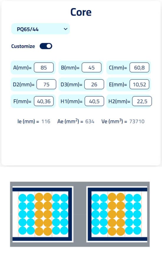
Now that we’ve switched to the LLC topology, the distribution of losses has changed significantly, allowing us to reduce the core size to a standard PQ65/54 or PQ65/44 with a lower profile. By adjusting the turns and core size, we can achieve 10 turns on the primary side and 5 on the secondary, resulting in a design similar to Figure 3 with the custom core option.
This could be a great option for the F1 Converter. However, we need to keep in mind that time is often a critical factor in project development. In order to save time, we can use standard materials and make some modifications to the design. For example, we can use a PQ65/54 core with 9 turns on the primary side, as shown in Figure 4. This will result in a slightly larger size but will still provide satisfactory performance for the F1 Converter.
Conclusions
In the highly competitive world of F1, it is essential to have access to the best materials, tools, and people to stay on top.
Having the most efficient Converter, which reduces weight, size, and increases performance, is crucial for success. Traditionally, designing a Converter can be a time-consuming process that requires extensive testing.
However, with Frenetic tools and support, you can have a complete design in minutes, allowing you to stay ahead of the competition.

